Speck Electronics ASC User Manual
Page 13
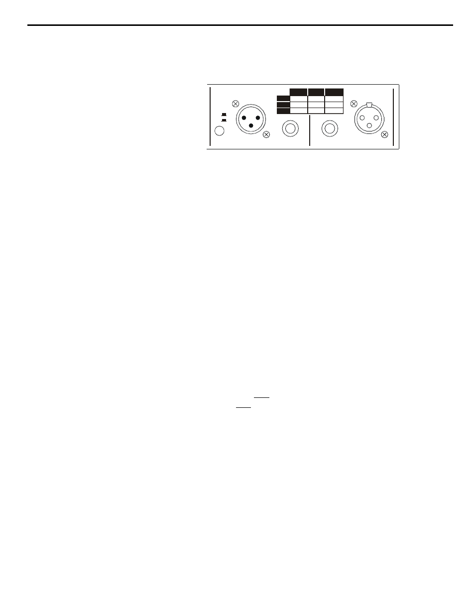
The input of the ASC has a balanced 1/4” jack and a balanced XLR
connector (Figure 2). These inputs are internally wired in parallel and
there is no operational difference between one or the other. The two
inputs can not be used simultaneously. The 1/4” input jack will accept a
1/4” TRS plug for balanced operation, or a 1/4” mono plug for
unbalanced operation.
The output of the ASC has a balanced 1/4” jack and a balanced XLR
connector (Figure 2). These inputs are internally wired in parallel and
there is no operational difference between one or the other except on the
Model ASC-T (see below).
A legend is provided on the rear panel to be used as a guide for the
proper configuration of input and output connectors.
The ASC with the optional output transformer gives you two choices of
balanced outputs; electronic active balanced at the 1/4” TRS jack or
transformer balanced at the XLR connector. On the Model ASC-T, the
transformer is wired only to the XL connector and the balanced active
output is wired only to the to the 1/4” TRS jack.
To prevent the transformer from loading the electronic active output
circuit, the XL output is automatically disabled when the 1/4” TRS
output jack is used on the ASC-T version.
9
The Input
The Output
Transformer Option
(for Model ASC-T only)
Chapter 2 Installation Section
OUTPUT
INPUT
GND
LIFT
BAL. XLR BAL.
¼ UNBAL.¼
HIGH
GND
LOW
PIN 2
PIN 3
PIN 1
TIP
RING
SLEEVE
TIP
SLEEVE
Figure 2. Input & Output Connectors