Iring, Iagrams – Southbend B-Series User Manual
Page 37
G
AS
C
ONVECTION
O
VENS
OPERATOR’S MANUAL 1181887 REV 9 (10/14)
PAGE 37
OF 44
W
IRING
D
IAGRAMS
A wiring diagram is located on the side of the control panel assembly. Wiring diagrams also appear on the following pages
of this manual. Which wiring diagram is appropriate depends on the voltage and type of controls.
Index of Wiring Diagrams
Page Number
Voltage and Type of Controls
Page 38
120 Volt Models with Standard Controls
Page 39
208-240 Volt Models with Standard Controls
Page 40
120 Volt Models with Cycle/Cook & Hold Controls
Page 41
208-240 Volt Models with Cycle/Cook & Hold Controls
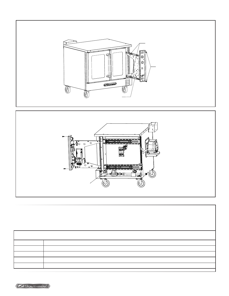
Accessing Control Panel
Components
Accessing Control Panel
Components
SLIDE RELEASE LEVERS
THUMB
SCREWS
LOCATION OF
WIRING DIAGRAM
SHUTOFF SWITCH
T
ROUBLESHOOTING