Sioux Tools ST2L1410 User Manual
Page 2
2
SPECIFICATIONS
Free Speed ...................................... 3,500 RPM
Air Pressure .................................... 90 psig max.
(6.2 bar / 620 kPa max.)
Average Air Consumption ............. 4 CFM (0.11m3/M)
Air Inlet Thread Size ....................... 1/4"-18 NPT
Air Supply Hose Size ...................... 3/8" ID (9.5 mm ID)
Air Supply Hose Length ................. 30' max. (9.14 m max.)
Weight ............................................. 2.4 lbs (1.1 kg)
Specifications at 90 psig (6.2 bar, 620 kPa)
DECLARATION OF CONFORMITY
We, Sioux Tools Inc., 250 Snap-on Drive, P.O. Box 1596, Murphy, NC, 28906, USA, declare under our sole responsibility that the products
ST2L1410
to which this declaration relates are in conformity with the following standard or standards or other normative document or documents:
EN 792, EN 292 Parts 1&2, ISO 8662, Pneurop PN8NTC1
following the provisions of
89/392/EEC as amended by 91/368/EEC & 93/44/EC Directives.
February 1, 2004
Murphy, North Carolina, USA
Date and place of issues
Gerald E. Seebeck
President
Sioux Tools Inc.
Name and position of issuer
Signature of issuer
*Sound Pressure
*Sound Power
*Vibration
Catalog No.
dBA
dBA
m/s2
ST2L1410
82.1
94.8
Less than 2.5
*per PN8NTC1
*per PN8NTC1
*per ISO 8662
SOUND AND VIBRATION READINGS
Application
The Surface Processing Tool is specially designed for removal of thick sealer, undercoat, window frame glue, asphaltic sheet, rust and
paint and many other general purpose removal jobs.
This air tool features a thermally balanced air motor design (patent # 5,383,771) that provides a more comfortable tool surface
temperature. The elastomer cover is an integral part of the tool and should not be removed.
Piping System
The piping system should be large enough to avoid an excessive pressure drop under maximum flow conditions. All pipe fittings and
hose outlets should be 1/2" (12.7mm) and should be arranged so there are no low spots that collect water which cannot be drained
daily.
Accessories are available for air tight connections.
Air Compressor
The air compressor should have sufficient capacity to deliver .52 cfm (3.56 scfm) at 90 psig (6.2 bar, 620 kPa) at each outlet while the
tool is running. The receiver tank should have sufficient capacity to provide surge balance for each air tool.
Air Strainer
An air strainer is built into the removable air inlet bushing located at the rear of the air tool. To clean, remove the bushing and use an air
hose to blow dirt and other particles from the screen and bushing. Before reinstalling the air inlet bushing, check the O-ring for
damage. If it is damaged, replace it with a new O-ring to prevent air leakage. Torque the air inlet bushing to 120 ñ 30 lbs. in.
Exhaust Deflector
The exhaust deflector, at the rear of the air tool, should be turned to direct the exhaust away from the user, other personnel and
sources of flame before using the tool.
Operation
WARNING
Read, understand and follow Safety Information in the front of this manual.
1. Before each use, inspect tool for damage.
2. Secure the vertical grip included and attach an air hose connector with suitable sealing material.
3. Choose the suitable abrasive brush belt depending on the surface and the material which you intend to remove. Ensure working
surface is dry and free of grease or oil.
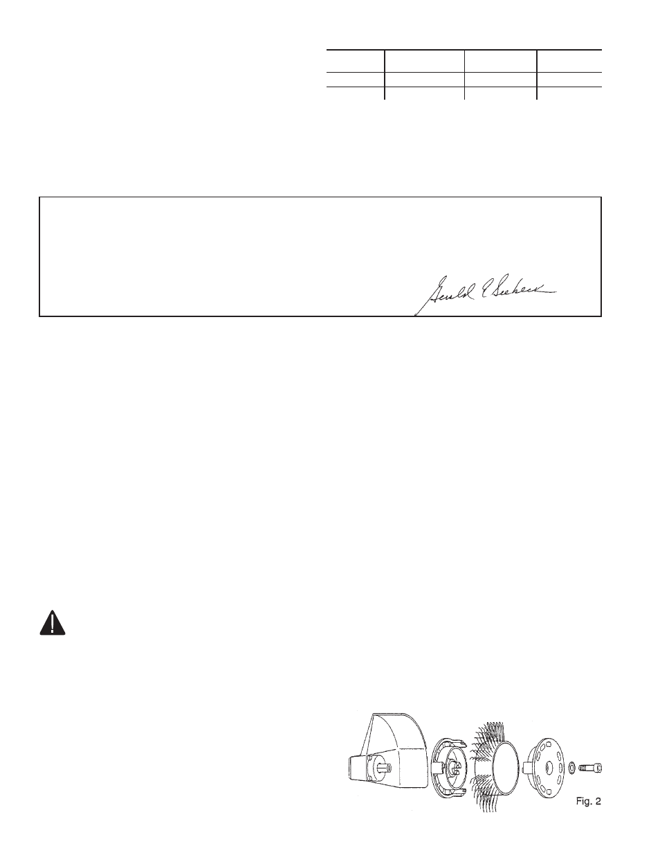
4. Assemble the abrasive belt to the tool correctly with the adapter
and the specific screw, disconnecting the air supply. See Fig. 2.
Be sure the brush bristles are facing in correct direction for
rotation of the tool. See page4.
5. This tool is started by depressing the throttle lever and tilting the
safety lock to the forward direction. This tool returns to the OFF
position when the lever is released.
6. Hold the tool by both the body and the vertical grip.