Notice – Remy 55SI™ ALTERNATOR User Manual
Page 2
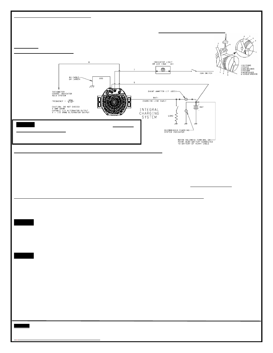
BELT TENSIONING INSTRUCTIONS: Improper belt tension can cause premature alternator failure. If the belt must be
tightened manually, place a wood block between the alternator and pry bar, as illustrated below. Pry as close to the center
of the unit as possible. Use a torque wrench to tighten mounting bolts to the proper torque as specified in vehicle or engine
manufacturer’s specifications for belt tension and mounting bolts torque. DO NOT OVER TIGHTEN BELT!
FIGURE 2
–
TYPICAL WIRING DIAGRAM Note: Alternator will function without
connecting the S, I & R terminals
RECOMMENDATION FOR DETERMINING APPROPRIATE CABLE SIZE
CHARGING LINE CABLE DROP SHOULD NOT EXCEED 0.5 VOLTS (ALTERNATOR OUTPUT [B+] TERMINAL TO
BATTERY POSITIVE TERMINAL AT FULL OUTPUT). FOR OBTAINING ADDITIONAL WIRING INSTALLATION
INFORMATION, SEE HEAVY DUTY APPLICATION MANUALS OR CONTACT A REMY INC. REPRESENTATIVE.
REMOTE SENSE
™ TECHNOLOGY senses the voltage level at the batteries or similar location where battery system
voltage can be read and adjusts alternator output. A direct connection from the a
lternator’s Remote Sense™ terminal to the
battery provides improved system voltage readings and optimizes state of charge. (Go tfor a more
descriptive explanation of Remote Sens
e™ technology)
TERMINAL DESCRIPTIONS (Alternator will function without connecting the S, I or R terminals):
“POS” Terminal - Output terminal connects to the positive (+) battery terminal.
“R” Terminal - Relay terminal carries half system voltage and may be used for certain types of control relays, charge
indicators, tachometers or similar devices. The current draw should not exceed four (4) amperes. Frequency = RPM/6.67.
Notice!
Do not install the Remote Sense
™ terminal lead to this terminal.
“I” Terminal - The Indicator lamp/ignition terminal carries full system voltage. Current draw should not exceed one (1)
ampere. It is recommended that current is not drawn from this terminal.
Ground Screw
– Ground lead ensures alternator is grounded and is strongly recommended for optimum performance.
“S” Remote Sense™ Terminal - Monitors battery system voltage at the battery or a common distribution point.
Notice!
Do not connect anything but the Remote Sense™ terminal line to this terminal. The “R” Terminal is not the
Remote Sense™ terminal.
♦ If installing this alternator with Remote Sense™ terminal in a vehicle that does not have a sense line, connect a fused
(5 Amp) insulated wire from the Alternator Voltage Sense terminal to the positive (+) battery terminal or the common
distribution point at the starter solenoid battery (+) terminal. Connection of this terminal is best for optimum performance;
however, the alternator will function without being connected.
Use a #16 gauge red insulated wire,
preferably with a 1/4” ID Convoluted Polyethylene Conduit. Also install a
standard inline fuse holder with a protective cap. Use a low voltage automotive standard blade style fuse, 5 Amp.
Only connect the Remote Sense
™ terminal line to the Remote Sense™ terminal. The “R” and “I” Terminals are Not
the Remote Sense™ Terminal!
Relay terminal output is
1/ 2 system voltage
NOTICE!
FOR VEHICLES EQUIPPED WITH A BATTERY
DISCONNECT SWITCH.
NEVER OPEN THE “BATTERY
SWITCH” WITH ENGINE RUNNING WHEN THE REMOTE
SENS
E™ TERMINAL IS CONNECTED TO THE BATTERY.
See note below for
determining the
appropriate cable size
NOTICE
- Only licensed Remy International, Inc. product and component parts should be used, and the use of other parts or modifications not approved
by Remy International, Inc. will void all applicable warranties. The failure to carefully follow these Installation Instructions, set forth above, will void all
applicable warranties. DELCO REMY is a registered trademark of General Motors Corporation, licensed to Remy International, Inc. Pendleton, IN 46064.
©
2012 Remy International, Inc. All rights reserved
2
Technical support: USA 800 854 0076, Mexico 01 800 000 7378, Brazil 0800 703 3526, South America 55 11 2106 6510 or visit delcoremy.com