Remy 24SI™ ALTERNATOR User Manual
Page 2
Technical support: USA 800 854 0076, Mexico 01 800 000 7378, Brazil 0800 703 3526, South America 55 11 2106 6510 or visit
delcoremy.com
NOTICE
- Only licensed Remy International, Inc. product and component parts should be used, and the use of other parts or modifications not approved
by Remy International, Inc. will void all applicable warranties. The failure to carefully follow these Installation Instructions, set forth above, will void all
applicable warranties. DELCO REMY is a registered trademark of General Motors Corporation, licensed to Remy International, Inc. Pendleton, IN 46064.
©
2012 Remy International, Inc. All rights reserved
2
PULLEY INSTRUCTIONS: Use pulley from old alternator if this alternator does not have a pulley or pulley supplied is different from the
one on alternator being replaced. NOTICE! When changing the pulley, keep the alternator shaft in the horizontal position and do
not apply any pressure to end of the shaft. Internal damage may occur if the shaft is pushed back and turned. If there were
spacers when the fan and pulley were removed, make sure all spacers are replaced when installing the pulley on this alternator. Hold the
shaft by placing a hex wrench in the hexagonal hole in the shaft while removing or installing the pulley. Tighten the pulley nut to 95-
108 N-m (70-80 lb ft).
BELT TENSIONING INSTRUCTIONS: Improper belt tension can cause premature alternator failure. If the
belt must be tightened manually, place a wood block between the alternator and pry bar, as illustrated at
right. Pry as close to the center of the unit as possible. Use a torque wrench to tighten mounting bolts to the
proper torque as specified in vehicle or engine manufacturer’s specifications for belt tension and mounting
bolts torque. DO NOT OVER TIGHTEN BELT!
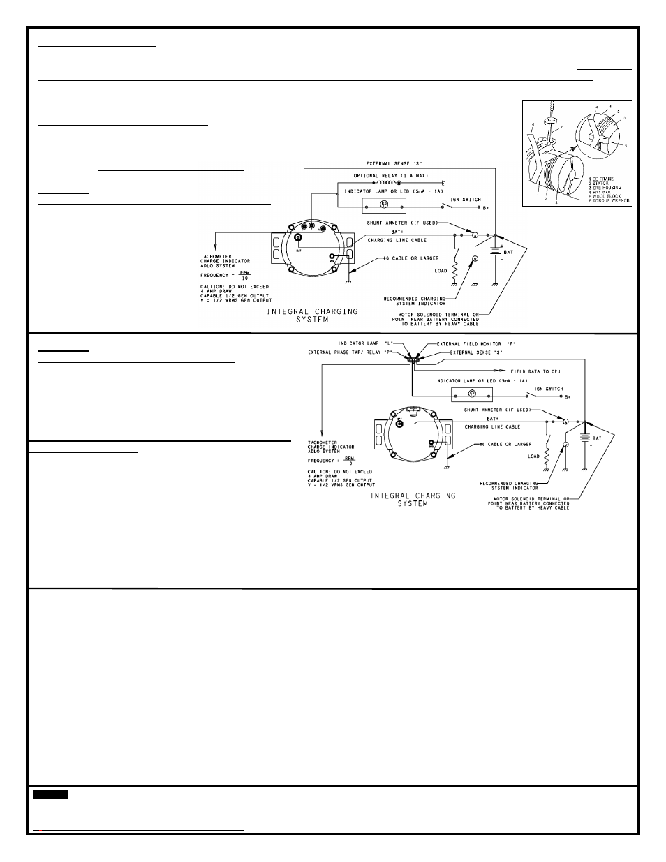
FIGURE 3 -
TYPICAL WIRING DIAGRAM STUD CONNECTORS
NOTE: Remote sense is optional
FIGURE 4 -
TYPICAL WIRING DIAGRAM
– 4 PIN PLUG
NOTE: Remote sense is optional
TERMINAL DESCRIPTIONS (P, L, F and S terminal
connections are optional:
“B+” Terminal - Output terminal connects to the positive
(+) battery terminal.
“S” Remote Sense™ Terminal – Connect to system
voltage at the battery or a common distribution point.
“P” Terminal – Relay / Phase terminal carries half system voltage and may be used for certain types of control relays, charge indicators,
tachometers or similar devices. The current draw should not exceed four (4) amperes. Frequency = Alternator RPM/10
“L” Terminal - The regulator Lamp terminal connects to the ignition switch through an indicator bulb or LED.
On Stud terminal models can also serve as a 1.0 Amp current source, sink or both.
Ground Screw
– Ground lead ensures alternator is grounded and is strongly recommended for optimum performance
If installing an alternator with
Remote Sense™ terminal in a vehicle that does not have a sense line, connect a fused (5 Amp)
insulated wire from the Alternator Voltage Sense terminal to the positive (+) battery terminal or the common distribution point at the
starter solenoid battery (+) terminal. Connection of this terminal is best for optimum performance; however, the alternator will function
without
Remote Sense™ connected.
Use a #16 gauge red insulated wire,
preferably with a 1/4” ID Convoluted Polyethylene Conduit. Also install a standard inline fuse
holder with a protective cap. Use a low voltage automotive standard blade style fuse, 5 Amp.
Only connect the Remote Sense
™ terminal line to the Remote Sense™ terminal. The “R” and “I” Terminals are not the Remote
Sense™ Terminal!
RELAY TERMINAL OUTPUT
IS 1/ 2 SYSTEM VOLTAGE
PHASE TERMINAL OUTPUT
IS 1/ 2 SYSTEM VOLTAGE