Installing horizontal tail installing landing gear – ParkZone PKZ6080 User Manual
Page 10
EN
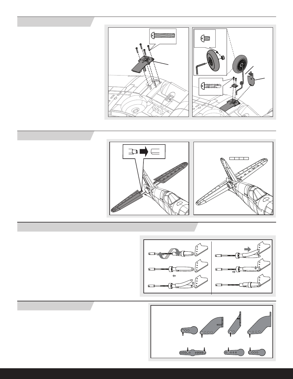
Tip: Turn the clevis on the linkage to change the length of the linkage
between the servo arm and the control horn.
• Pull the tube from the clevis to the linkage.
• Carefully spread the clevis, then insert the clevis pin into the
desired hole in the control horn.
• Move the tube to hold the clevis onto the control horn.
After binding a transmitter to the model receiver, set the trims and
sub-trims to 0, then adjust the clevises to center the control surfaces.
1.
4.
5.
6.
2.
3.
Fly the model at factory settings before making changes. For pilots who
wish for more control throw, adjust the position of the linkages on the servo
arms and control horns for increased travel.
Installing Clevises on Control Horns and Control Centering
Factory Settings
Rudder
Tail Wheel
Ailerons
Elevator
Arms
Horns
Installing Horizontal Tail
Installing Landing Gear
1. Slide the horizontal tail tube into the hole in the
rear of the fuselage.
2. Install the left and right horizontal tails onto the
fuselage as shown. Ensure the control horn
faces down.
3. Apply four pieces of tape to the fuselage mounts
(one on the top and bottom of each half of the
horizontal tail).
4. Attach the clevis to the elevator control horn
(see instructions for clevis connection).
5. When needed, disassemble in reverse order.
Intallation
1. Install the left landing gear door hinge (
G)
(marked L) in the wing clamp as shown.
2. Install the left landing gear plate (
A) (marked
with an L) in the wing using four screws (
B).
3. Install the left landing gear strut in the plate as
shown.
4. Install the left cover (
C) (marked L) on the strut
(
D) using two screws (E).
5. Install the wheel on the strut using the collar.
Make sure the bushing side of the wheel is
toward the bend in the strut.
6. Tighten the setscrew (
F) in the collar. Use a
small amount of threadlock to hold the setscrew
in the collar.
7. Install the right landing gear the same as the
left landing gear.
Removal
When needed, disassemble in reverse order.
3 X 10mm (2)
3 X 15mm (4)
B
A
C
D
G
E
3 X 4mm (1)
F
10