Nor-Cal CDG 160 OP Lit User Manual
Page 20
20
CDG160-OP-LIT
(2010-06)
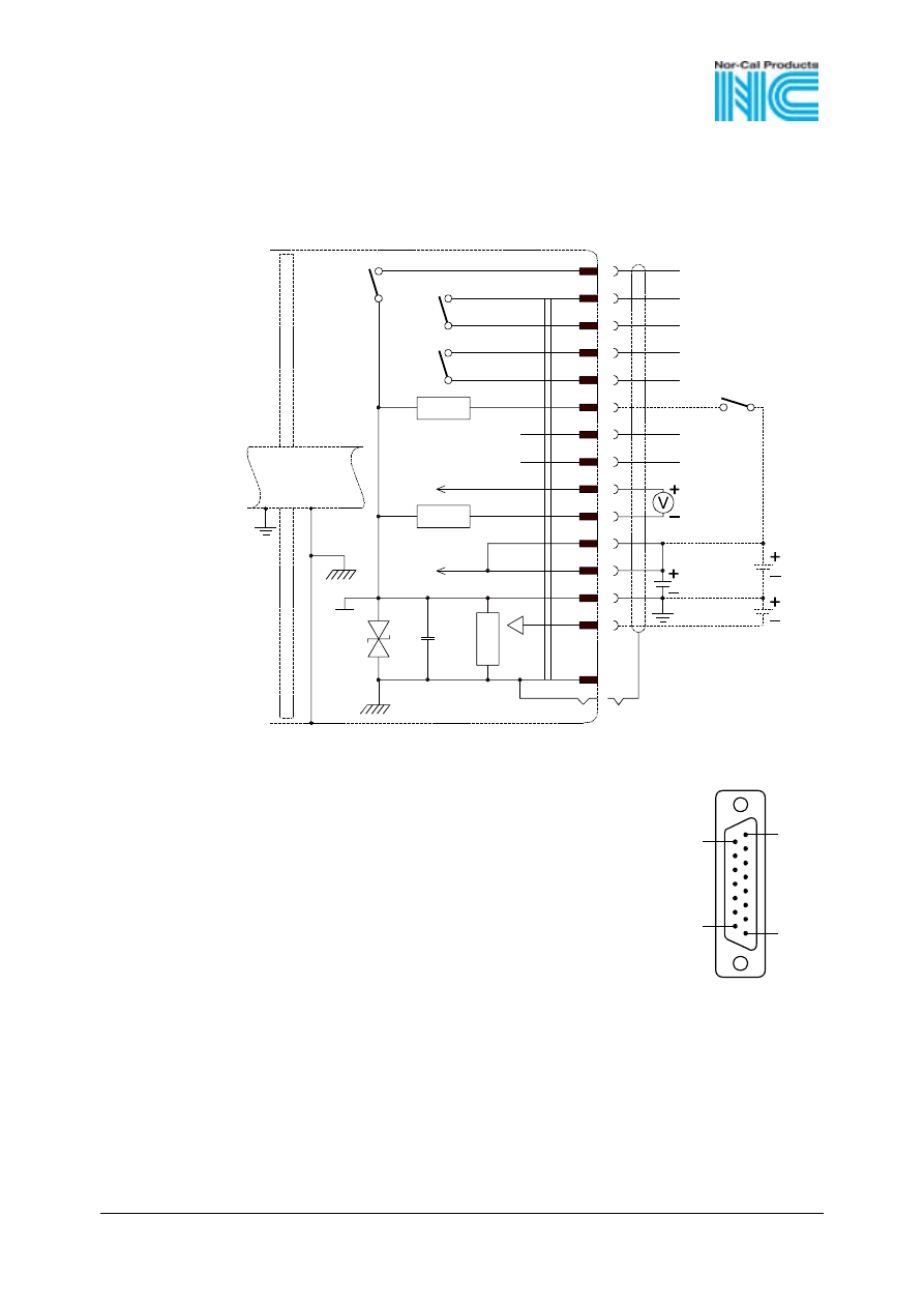
If no sensor cable is available, make one according to the
following diagram (cable length and conductor cross-
sections
→ 12).
15
8
9
1
15-pin
D-Sub
female
soldering
side
Electrical connection
Pin 1, 4
Relay SP1, closing contact
Pin 2
Signal ouput (measurement signal)
or thresholds SP1/2
Pin 3
Status
Pin 5
Supply common
Pin 6
Supply (-15 V)
Pin 7, 11 Supply (+21 ... +30 V or +15 V)
Pin 8, 9
Relay SP2, closing contact
Pin 10
Gauge identification
or Remote Zero Adjust
Pin 12
Signal common
Pin 13
RS232, TxD
Pin 14
RS232, RxD
Pin 15
Housing (Chassis Ground)
case
Connector case
case
15 V
15 V
21…30 V
Remote
Zero Adjust
1 M
4
1
8
9
10
Ident
13
14
2
TxD
RxD
12
7
11
5
15
100nF
18 V
10
6
3
SP1
SP2
Status