MTI Wireless Edge MT-900007 User Manual
Page 2
Installation Instructions for MT-900007
2
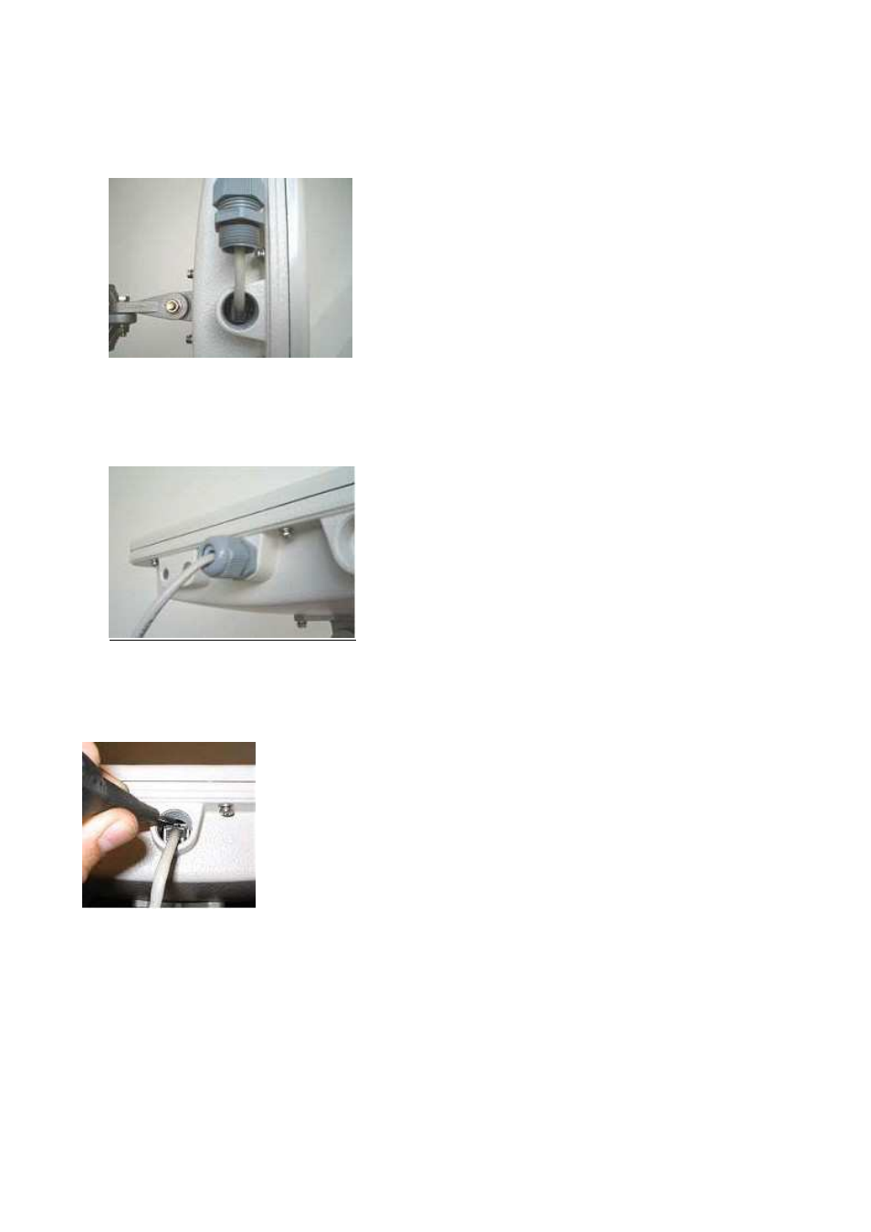
6.
Crimp the RJ45 connector to the CAT5 cable and click it into the RJ45 jack as shown in
Fig-3
Figure 3: RJ45 Connected Through M20 Threaded Hole
7.
Screw the gland into the M20 threaded hole and tighten as shown in Fig 4. The CPE is ready
for use.
Figure 4: View Showing RJ45 Connected to RJ45 Jack
8.
To disconnect the CAT5 cable, open the gland, release, and pull out the RJ45 connector
using a pointed tool such as 00 screwdriver, as shown in Fig-5.
Figure 5: Showing Release and Removal of CAT5 Cable