Sheet5, Drawing view11, Drawing view13 – MTI Wireless Edge MT-120034 User Manual
Page 2: Step 1, Step 2
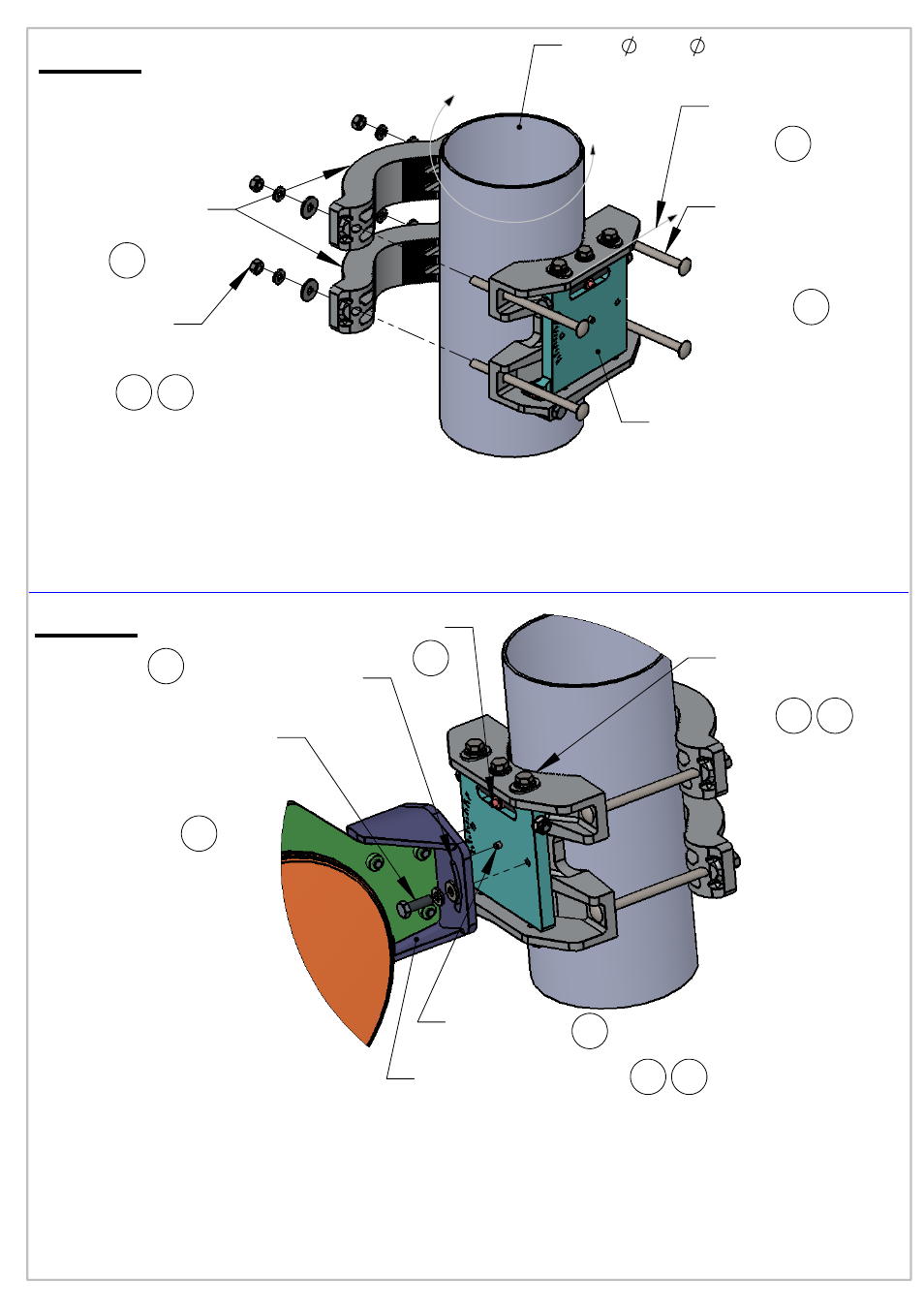
Mast 2.5"- 4.5" outer diameter
Holder Bracket
(2pl.)
Hex nut M6
Washer Spring M6
Washer Flat M6
(4pl.)
Mounting Lock Bolt
(Round
Head Square)
(4pl.)
Mounting Kit
Sub Assy
Sight View Line
2
1
Step 1
Screw Hex Cap
Washer Spring
Washer Flat
(2pl.)
Grease surface
around the slots
from both sides
Antenna Dish Base
Pivot
Pin
Mounting Kit
Pin
Azimuth lock Bolts
(6pl.)
Notes:
Insert the Mounting Lock Bolts (4pl.) to the sockets, attach to the mast and
1.
assemble Holder Brackets (2pl.) on the Bolts. Hand tight the nuts & washers (4pl.)
on the Bolts without finally fastening.use #11 open end, or deep socket wrench
2. Roughly Rotate and aim the Mounting Kit while the Sight view line towards the target.
3. Use tightening Torque of 8Nm on Mounting Lock Bolts Nuts (4pl.)
1
1 3
Step 2
Notes:
4. Use grease on marked recommended places and on Adjustment Bolts
(Elevation & Azimuth). (see drawing).
5. Attache Antenna Dish Base to Mounting Kit Pin and Pivot pin.
6. Assembly Bolts and washers (2pl.) to the M.K Sub Assy use tightening torque of 6Nm .
make sure azimuth lock bolts (6pl.) fasten with tightening torque of 6Nm.
7. After fine adjustment, use tightening lock torque of 8
Nm on Azimuth Lock Bolts (6pl.)
and Elevation Lock Bolts (2pl.). Use #11 open end, or deep socket wrench.
8. Adjustment Bolts (Elevation+Azimuth) must be greased at all time.
6
4
5
6
5
5
6 7