Connect opener power cables, Connect the transformer, Solar instructions on page 21) – Mighty Mule MM402 User Manual
Page 24: Step 1, Step 2, Step 3, Make sure the power switch is off
14
Mighty Mule FM402 Installation Instructions
rev 082211
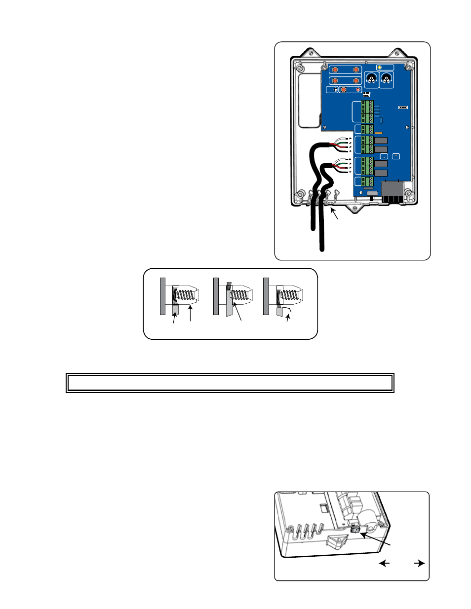
Connect Opener Power Cables
Step 1
Bring FIRST power cable into the control box through a strain relief slot,
leaving enough wire to reach the FIRST OPR. terminal block.
Insert the individual power cable wires into appropriate terminals on the
FIRST OPR. terminal block (white to WHT; green to GRN; red to RED;
black to BLK). Tighten the set screws. A dab of petroleum jelly on each
terminal will help prevent corrosion.
Step 2
Pull the 36' second opener power cable through the PVC conduit and
secure in the driveway slot/trench (see pages 6 and 14).
Step 3
Insert the SECOND power cable into a strain relief slot at the bottom
of the control box, leaving enough wire to reach the SECOND OPR.
terminal block.
Insert the individual power cable wires into appropriate terminals on
the SECOND OPR. terminal block (white to WHT; green to GRN; red to
RED; black to BLK). Tighten the set screws.
Connect the Transformer
(*Solar Instructions on Page 21)
NEVER USE TRANSFORMER AND SOLAR PANEL(S) AT THE SAME TIME!
IMPORTANT INFORMATION ABOUT LOW VOLTAGE WIRE:
• The only wire acceptable for use with GTO products is 16 gauge stranded, low voltage, direct burial wire. This
particular gauge enables the transformer to provide an adequate charge through the control board to the battery
at distances up to 1000'.
• DO NOT use telephone wire or solid core wire. Unlike stranded wire, these types of wire are inadequate for use
with your gate opener system.
• NEVER splice wires together. Splicing permits corrosion and seriously degrades the wire's ability to carry an
adequate current.
Step 1
Make sure the power switch is OFF.
Step 2
Select the electrical outlet where you will plug the transformer. Measure
the distance from this outlet to the control box following the path
where the wire will be laid. After you have measured how much wire is
needed, cut the wire to the appropriate length (up to 1000').
FIRST Opener
Power Cable
SECOND Opener
Power Cable
Strain Relief Slots
(Battery Wires Not Shown)
VAR5
VAR6
K1
PF1
K2
BATT
+
BATT
–
K3
K4
VAR4
VAR3
VAR2
VAR1
MIN
MAX OFF
JP1
REMOVE JUMPER FOR
PUSH TO OPEN OPTION
120
SEC.
G
TO Inc.
Tallahassee, FL
R4722
STALL FORCE
OPEN < JOG > CLOSE
PWR.
SET
LIMIT
1st OPR.
2nd OPR.
STATUS
AUTO CLOSE
SFTY.
EXIT
CYCLE
EDGE
SENSOR
COMMON
LOCK+
LOCK–
WHT
GRN
RED
BLK
WHT
GRN
SECOND OPR
.
FIRST OPR
.
RED
BLK
14 VAC
OR
SOLAR
ON OFF
Correct
Wrong
Screwed into
wire insulation.
Exposed strands
of wire.
Wrong
Wire Terminal
Block
ON/OFF
Switch
ON/OFF