Installation overview for pull-to-open gates, Gate in the open position, Gate in the closed position – Mighty Mule MM402 User Manual
Page 16
6
Mighty Mule FM402 Installation Instructions
rev 082211
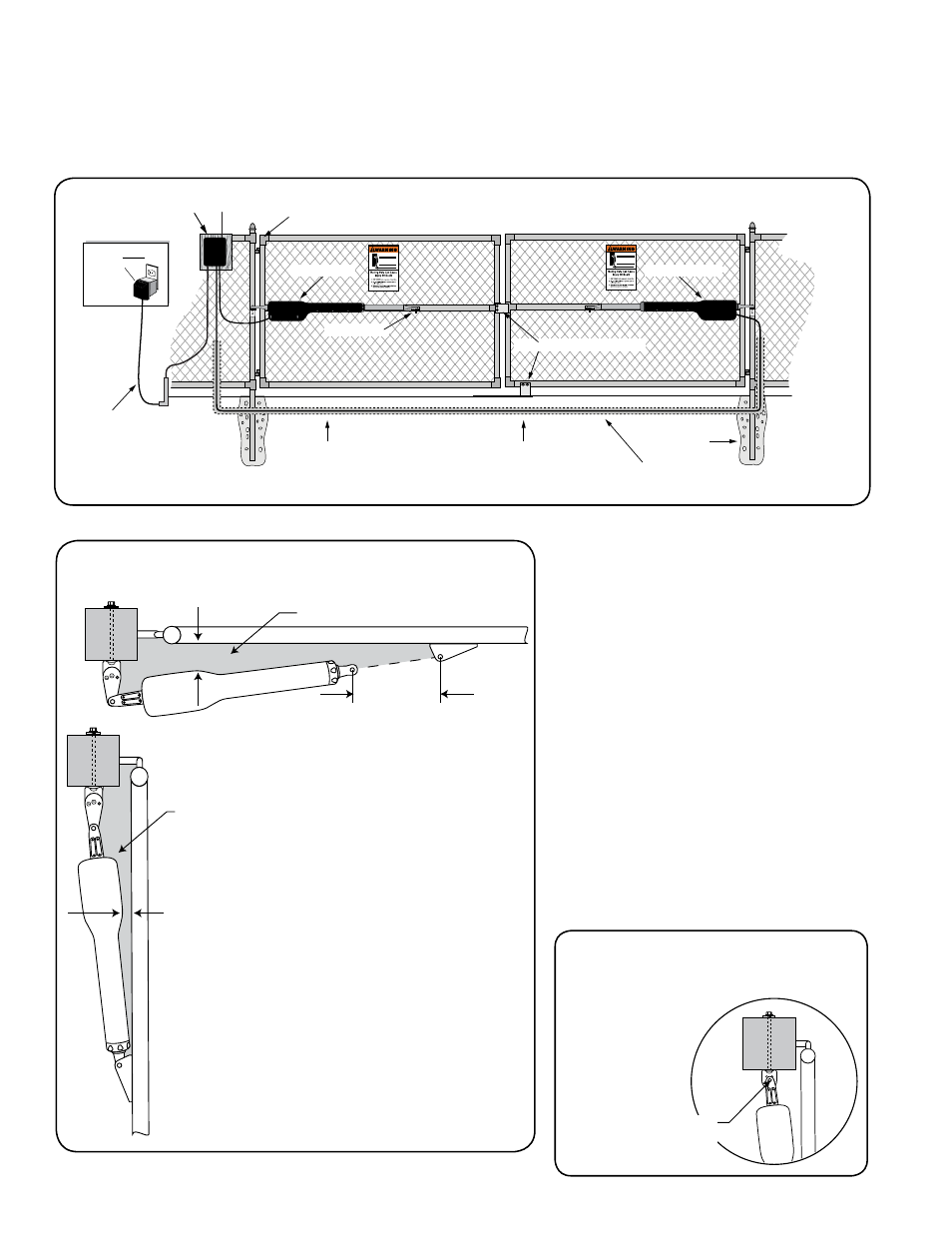
If the gate post is larger than
6" the Post Pivot Bracket can
be removed and the center
hole of the Post
Bracket can be the
mounting point
for the gate
opener.
Center hole of
post bracket
Installation Overview for Pull-To-Open Gates
PUSH-TO-OPEN installation instructions begin on page 19.
Example of an installation on a chain link fence:
IMPORTANT: To achieve the most efficient
leverage for the gate opener and ensure long
trouble free service, the gate opener needs to
be installed within the following parameters.
The diagram at left shows the optimum
position for gate opener arm in relation to
the gate in the open and closed positions.
Be sure the position of the gate opener and
brackets allows for 1" of clearance between
the gate and the opener in both the open and
closed position, at the same time maintaining
a maximum distance of 13" from the end of the
retracted opener arm to the gate bracket with
the gate in the closed position.
36' power cable allows the control
board to control the SECOND
gate opener (run in PVC conduit)
You will need to trench across the
driveway in order to lay conduit for
the second opener power cable.
120 Volt indoor
Transformer
(surge protector
not supplied)
Fence Post
Set in Concrete
Run 1000' (max.) of low
voltage wire to control box
from transformer
(wire not included).
PVC conduit (not included)
to protect wire from lawn
mowers and weed eaters.
Gate Swings Evenly and Freely
Hung Firmly and Plumb
Control Box / Battery Box
First Opener
Second Opener
Closed Position Stop Plates
Gate Bracket
1" minimum
Gate in the
OPEN POSITION
Pinch Area
Gate in the
CLOSED POSITION
Pinch Area
1" minimum
13" or less