Personalize your transmitter setting, Step 1, Step 2 – Mighty Mule MM362-D User Manual
Page 28: Step 3
18
Mighty Mule 362-D Installation Instructions
rev 07/19/11
Personalize Your Transmitter Setting
All GTO transmitters have a standard setting and are ready to operate
your Mighty Mule Gate Opener. For your safety and security, we
strongly recommend that you replace the factory setting with your own
personal setting.
NOTE: If you have multiple transmitters, you should adjust all of
them at this time.
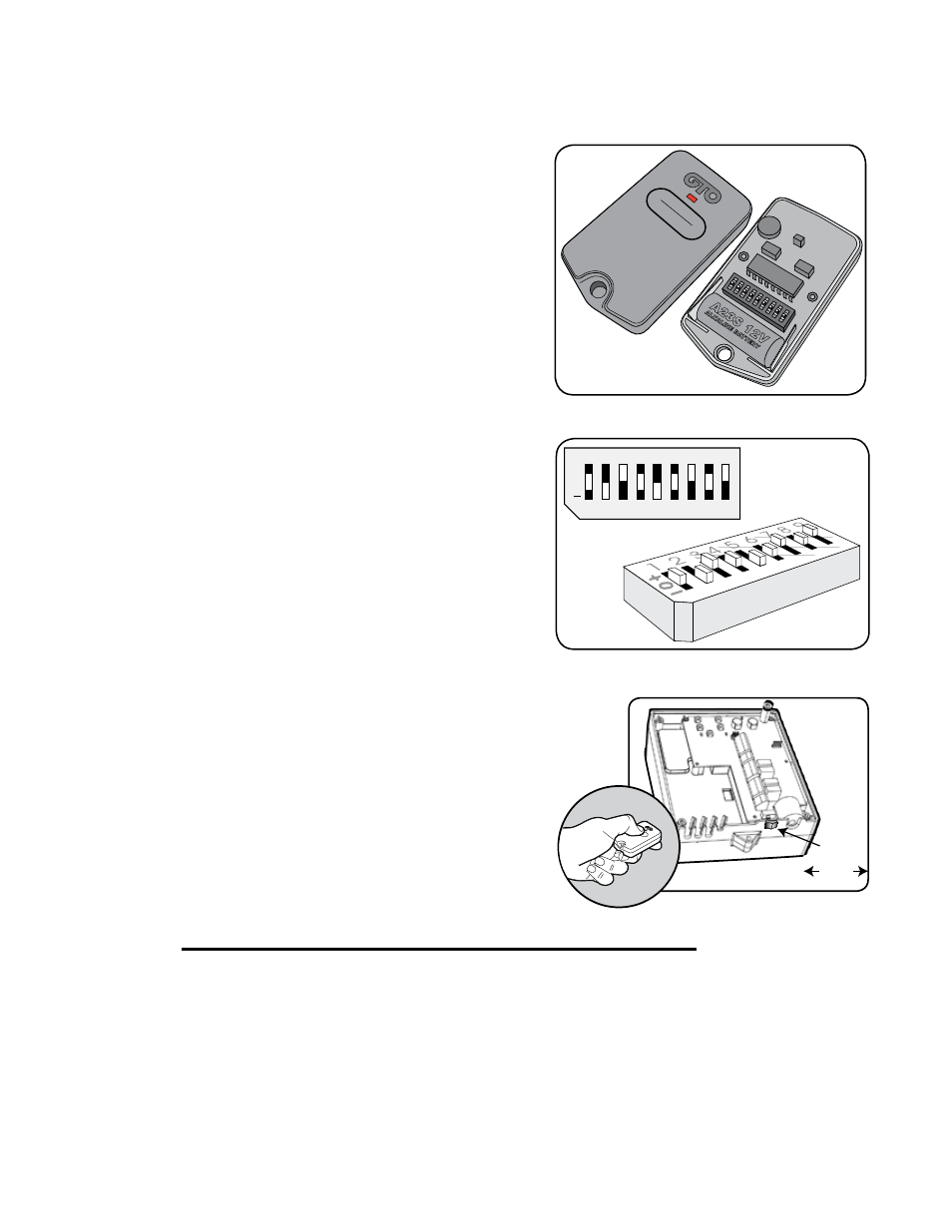
Step 1
Use a small phillips head screw driver to remove the transmitter cover.
Step 2.
Set the transmitter DIP switches using a small screwdriver. There are
nine (9) transmitter DIP switches; each can be placed in three different
positions (+, 0, –). DO NOT set all the switches in the same position,
such as all +, all 0, or all –. Once the DIP switches have been reset,
replace and close the access cover.
WARNING: No other adjustments should be made inside the
transmitter.
Step 3.
Program the new setting in the control board memory.
A. Slide the control box ON/OFF switch to the OFF position.
B. Press and hold the transmitter button while sliding the ON/OFF
switch to the ON position.
C. Continue to hold the transmitter button until the alarm sounds
(3-5 seconds).
D. Release the transmitter button. The new transmitter setting is
now programmed.
E. Verify that the transmitter operates the gate.
NOTE: It is NOT necessary to remove the cover of the control box to
program the new transmitter code, but when the control box cover is
removed the receiver range is reduced to less than 5 feet.
FCC WARNING: Changes or modifications to this unit not expressly approved by the party responsible for compliance could void the user’s
authority to operate the equipment. In accordance with FCC Part 15, Section 15.21, the manufacturer is not responsible for any radio or TV
interference caused by unauthorized modifications to this equipment. Such modifications could VOID the user authority to operate the equipment.
NOTE: This equipment has been tested and found to comply with the limits for a Class B digital device, pursuant to Part 15 of the FCC Rules.
These limits are designed to provide reasonable protection against harmful interference in a residential installation. This equipment generates,
uses and can radiate radio frequency energy and, if not installed and used in accordance with the instructions, may cause harmful interference to
radio communications. The external solid wire antenna (10”) was used during FCC testing. Substitutes should not be used.
However, there is no guarantee that interference will not occur in particular installations. If this equipment does cause harmful interference to radio
or television reception, which can be determined by turning the equipment off and on, the user is encouraged to try to correct the interference
by one or more of the following measures: • Increase the separation between the equipment and the receiver. • Connect the equipment into an
outlet on a circuit different from that which the receiver is connected. • Consult the dealer or an experienced radio/TV technician for help.
+
0
ECE
1 2 3 4 5 6 7 8 9
ON/OFF
Switch
ON/OFF
1
2
3
4
5
6
7
8
9
ECE
A23S 12V
ALKALINE BA
TTERY
+
0
–
LED