Connect battery harness to control board, Step 6, Step 1 – Mighty Mule MM362-D User Manual
Page 25: Step 2, Step 3, At the ac outlet, strip
rev 07/19/11
Mighty Mule 362-D Installation Instructions
15
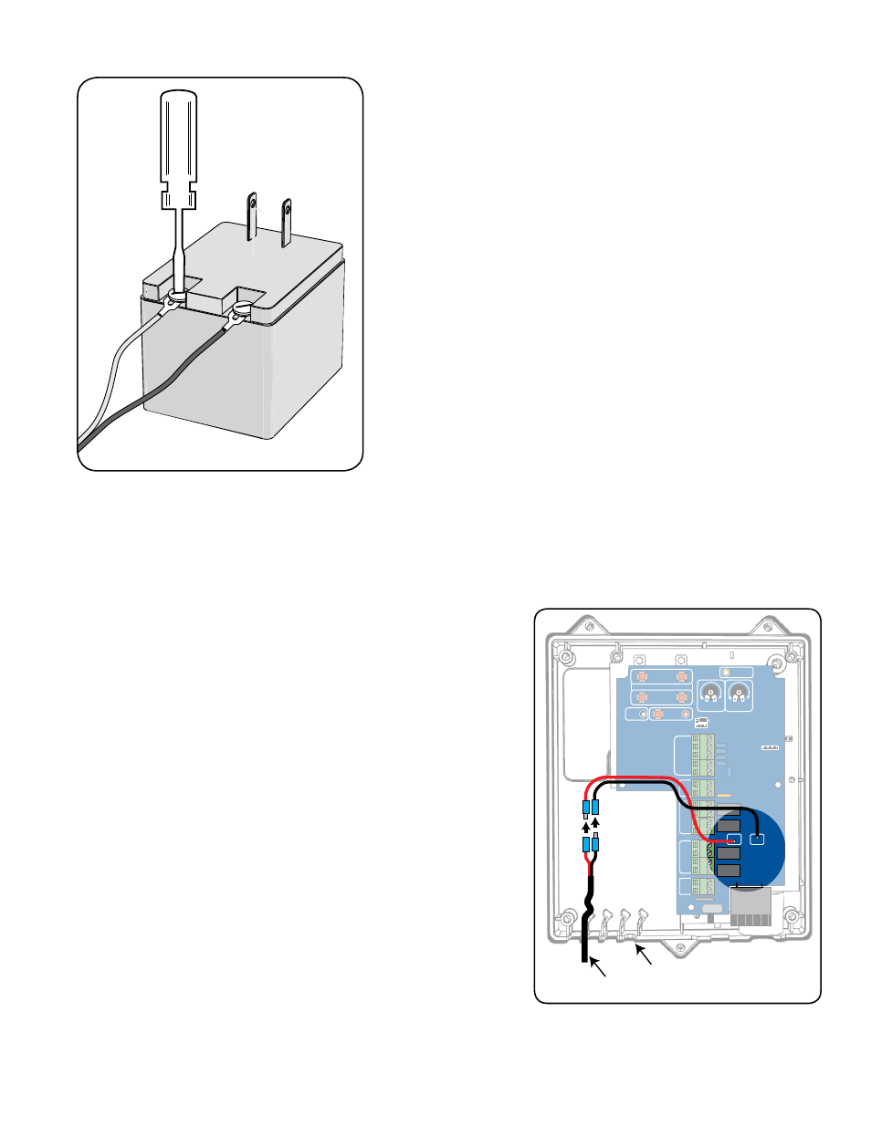
Step 6
At the AC outlet, strip
1
/
2
" of insulation from the ends of the low voltage
wire. Attach these stripped ends to the transformer terminals. A dab of
household petroleum jelly on each terminal will help prevent corrosion.
We suggest adding crimp on fork lugs to the end of each wire before
attaching it to the transformer.
Make sure the exposed wires do not touch each other!
Connect Battery Harness to Control Board
Step 1
Make sure control box is OFF. Locate the BATTERY wires from the
CONTROL BOARD marked BATT + and BATT –.
Step 2
Run the battery harness wires into the control box through a strain relief
slot, leaving enough wire to reach the battery wire plugs.
Step 3
Plug the BLACK battery harness wire into the BLACK wire (BATT –
terminal), and the RED battery harness wire to the RED wire (BATT +
terminal). Wire correctly;
reverse connection will damage control
board.
VAR5
VAR6
K1
PF1
K2
BATT
+
BATT
–
K3
K4
VAR4
VAR3
VAR2
VAR1
MIN
MAX OFF
JP1
REMOVE JUMPER FOR
PUSH TO OPEN OPTION
120
SEC.
G
TO Inc.
Tallahassee, FL
R4722
STALL FORCE
OPEN < JOG > CLOSE
PWR.
SET
LIMIT
1st OPR.
2nd OPR.
STATUS
AUTO CLOSE
SFTY.
EXIT
CYCLE
EDGE
SENSOR
COMMON
LOCK+
LOCK–
WHT
GRN
RED
BLK
WHT
GRN
SECOND OPR
.
FIRST OPR
.
RED
BLK
14 VAC
OR
SOLAR
ON OFF
Strain Relief Slots
Battery Harness Cable
from Battery