Adjust the stall force potentiometer setting, Set auto-close time, Step 3 – Mighty Mule MM362-D User Manual
Page 27: Step 4, Step 5, Step 6
rev 07/19/11
Mighty Mule 362-D Installation Instructions
17
Step 3
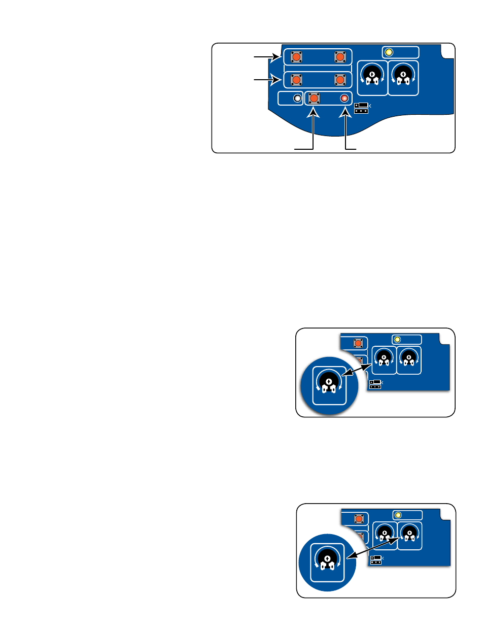
Press and HOLD the 1st Opener CLOSE
button on the control board and be prepared
to RELEASE the button when the gate reaches
the desired closed position/limit. Use the JOG
OPEN and CLOSE buttons to "fine tune" the
gate position if neccessary.
Step 4
With the gates in in the desired closed
positions PRESS and HOLD the SET LIMIT
button until the alarm and RED Light come on.
Then release the button.
NOTE: The opener must be extended more
than 7 inches to set limits.
Step 5
NOTE: When the control box cover is removed the receiver range is reduced to less than 5 feet.
Press the transmitter button once (within 5 feet of the control board) and allow the gates to fully open. The alarm will beep
once when both gates reach the OPEN LIMIT. This indicates the limits for both arms are programmed in memory.
Step 6
Press the transmitter button and allow the gates to fully close to verify that they stop at the desired positions. Repeat
Steps 2-5 if correction is needed.
Adjust the Stall Force Potentiometer Setting
The Stall Force
potentiometer controls the the amount of force the
opener will apply against an obstruction before it stops and reverses
direction within two seconds.
IMPORTANT: The Stall Force setting will need to be adjusted to
compensate for the weight and size of your gates. For safety reasons,
use the lowest possible setting to operate the gate.
The Stall Force
potentiometer on the control board operates like
a volume control on a radio. Use a small flat blade screwdriver to
turn the arrow in the center of the potentiometer. Adjust the sensitivity
from the MINIMUM position just to the point where the gates operate
smoothly without obstructing from their own weight or wind conditions.
NOTE: You may need to increase the stall force in cold weather
due to increased resistance from gate hinges.
Set Auto-Close Time
The Auto-Close determines how long the gate will remain open before
it automatically closes. The factory setting is OFF. Use a small flat
blade screwdriver, you can adjust the settings to OFF, or from 3 to 120
seconds.
NOTE: Auto-Close timer is disabled (gate will not automatically
close) if gate is not at the fully open position.
MIN
MAX OFF
REMOVE JUMPER FOR
PUSH TO OPEN OPTION
120
SEC.
STALL FORCE
OPEN < JOG > CLOSE
PWR.
SET
LIMIT
1st OPR.
2nd OPR.
STATUS
AUTO CLOSE
FIRST Opener
JOG Buttons
SET LIMIT Button
SET LIMIT Light
SECOND Opener
JOG Buttons
VAR5
VAR6
K1
PF1
K2
BATT
+
BATT
–
K3
K4
VAR4
VAR3
VAR2
VAR1
MIN
MAX OFF
JP1
REMOVE JUMPER FOR
PUSH TO OPEN OPTION
120
SEC.
G
TO Inc.
Tallahassee, FL
R4722
STALL FORCE
OPEN < JOG > CLOSE
PWR.
SET
LIMIT
1st OPR.
2nd OPR.
STATUS
AUTO CLOSE
SFTY.
EXIT
CYCLE
EDGE
SENSOR
COMMON
LOCK+
LOCK–
WHT
GRN
RED
BLK
WHT
GRN
SECOND OPR
.
FIRST OPR
.
RED
BLK
14 VAC
OR
SOLAR
ON OFF
MIN
MAX
STALL FORCE
VAR5
VAR6
K1
PF1
K2
BATT
+
BATT
–
K3
K4
VAR4
VAR3
VAR2
VAR1
MIN
MAX OFF
JP1
REMOVE JUMPER FOR
PUSH TO OPEN OPTION
120
SEC.
G
TO Inc.
Tallahassee, FL
R4722
STALL FORCE
OPEN < JOG > CLOSE
PWR.
SET
LIMIT
1st OPR.
2nd OPR.
STATUS
AUTO CLOSE
SFTY.
EXIT
CYCLE
EDGE
SENSOR
COMMON
LOCK+
LOCK–
WHT
GRN
RED
BLK
WHT
GRN
SECOND OPR
.
FIRST OPR
.
RED
BLK
14 VAC
OR
SOLAR
ON OFF
OFF
120
SEC.
AUTO CLOSE