Step 5, Step 6, Step 7 – Mighty Mule MM362-D User Manual
Page 19: Step 8, Gate in the open position, Gate in the closed position
rev 07/19/11
Mighty Mule 362-D Installation Instructions
9
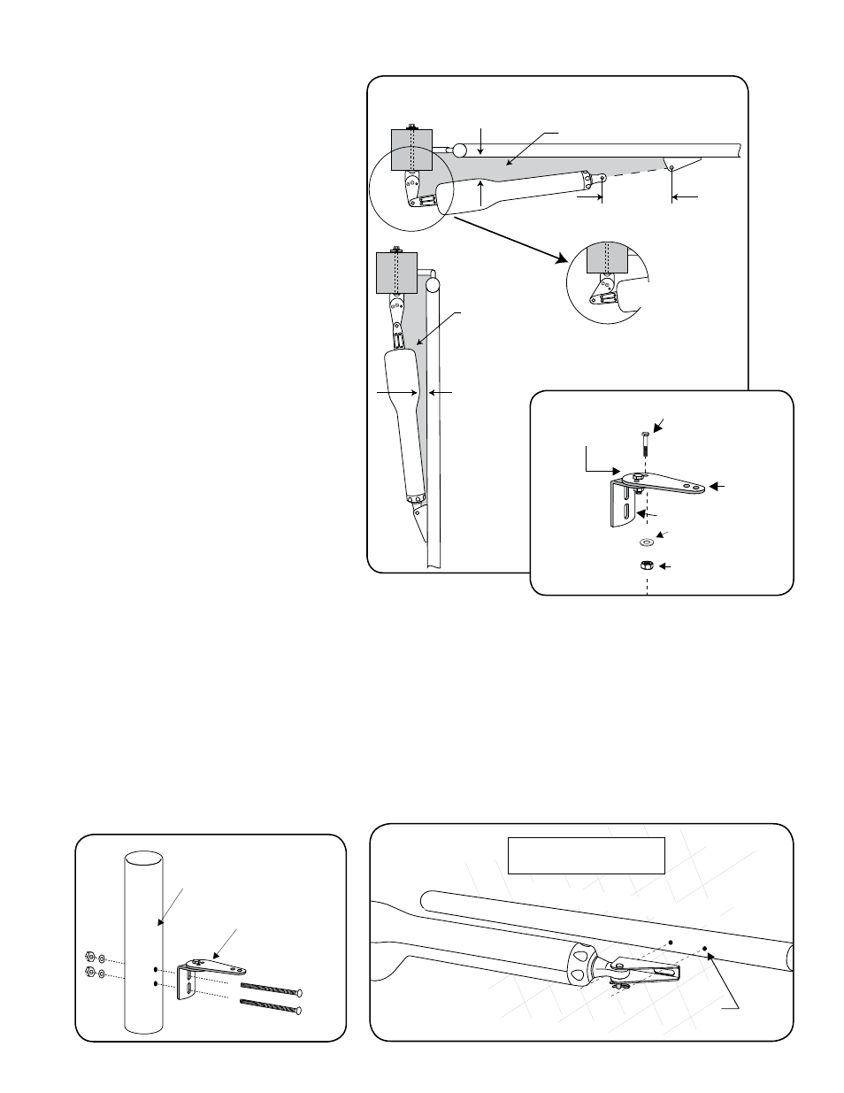
Step 5
Be sure the position of the gate opener and
brackets allows for 1" of clearance between
the gate and the opener in both the open
and closed position, while at the same time
maintaining a maximum distance of 13"
from the end of the retracted opener arm to
the gate bracket with the gate in the closed
position. This mounting position will give the
opener the most efficient leverage point for
operation and provides the least possible
pinch area
Step 6
After verifying that you have the best position
for the post pivot bracket in the open position,
insert the
5
/
16
" x 1
1
/
2
" bolt through the
aligned holes of the post bracket and post
pivot bracket to hold it in place. Remove the
clevis pin from the front mount and
while
supporting the gate opener, swing the gate
and gate opener to the closed position. Again,
check the clearance and be sure that the gate
opener is not binding at the post pivot bracket.
If you don't have the required clearance,
or if the gate opener is binding on the post
pivot bracket, remove the
5
/
16
" x 1
1
/
2
" bolt and
readjust the post pivot bracket.
TIP: Turn the post pivot bracket over for more
hole alignment options. You can also move the
entire post bracket assembly to different positions on the post.
Step 7
When the post bracket assembly is in the optimum position, reattach the opener to the gate bracket (gate in the open
position); recheck the gate opener level; make sure the brackets are clamped securely.
Step 8
Mark reference points for bolt holes on the post through middle of post bracket assembly slots. Mark reference points for
bolt holes on the gate cross member through middle of gate bracket slots. After marking your reference points, remove
the opener and brackets from the fence and gate.
1" minimum
Gate in the
OPEN POSITION
Pinch Area
Gate in the
CLOSED POSITION
Pinch Area
1" minimum
13" or less
Be sure gate opener
and bracket don't bind.
5
/
16
" x 1
1
/
2
"
Bolt
Post Pivot
Bracket
Determine Best
Hole Alignment
to Achieve
1" Clearance
Post Bracket
5
/
16
" Lock Nut
5
/
16
" Washer
Post Bracket
Assembly
Mark fence post through
middle of bracket slots
and drill
3
/
8
" holes through
post.
Gate In Open Position
Arm Fully Retracted
LEVEL horizontal cross member
Mark cross member through middle of gate
bracket slots and drill
3
/
8
" holes through cross member.