Connecting additional devices, Input connections, Ba t t – Mighty Mule FM500 Blue Board User Manual
Page 34: Au x r ly
31
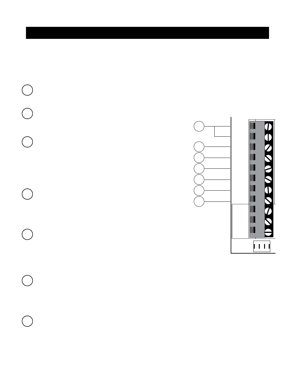
1 COM: Circuit common (reference for all logic input)
• Two (2) terminals to provide extra common connection point.
2 CYCLE: (Typically for use with doorbell button or hardwired key pad)
• Each activation at this input will cycle the operation as follows:
….→ OPEN → STOP → CLOSE → STOP → OPEN → …
3 SAFETY: (Typically for use with photo beam device, loop detector
or other non-contact sensors)
• Activation of this input while the gate is closing will cause the gate to
stop and return to the opened position.
• Activation of this input while the gate is opening has no effect (gate
will continue to open).
• Activation of this input while gate is idle will prevent gate from closing.
4 EXIT: (Typically for use with exit loop or wand)
• Activation of this input will open the gate if it’s not already at the
open position
• Activation of this input while at open limit will restart the auto close time
(if enabled).
5 SHADOW: (Typically for use with loop detector device)
• This input is only monitored when the gate is at the fully open
position. At any other position, activation of this input has no effect on
gate operation.
• Activation of this input while gate at the fully open position will
prevent gate from closing.
6 CLOSE EDGE: (Typically for use with safety edge device)
• Activation of this input while the gate is closing will cause the gate to
stop and reverse direction for approximately 2 seconds.
• Activation of this input while the gate is opening has no effect (gate will continue to open).
• Activation of this input while gate is idle will prevent gate from closing.
7 OPEN EDGE: (Typically for use with safety edge device)
• Activation of this input while the gate is opening will cause the gate to
stop and reverse direction for approximately 2 seconds.
• Activation of this input while the gate is closing has no effect (gate
will continue to close).
• Activation of this input while gate is idle will prevent gate from opening.
1
2
3
4
7
5
6
B
A
T
T-
1 2
3
4
ON
R
E
C
E
IV
E
R
LE
A
R
N
M
A
S
T
L
IM
IT
LE
A
R
N
S
LV
L
IM
IT
S
3
S
4
A
LM
S
2
O
FF
S
O
FT
S
TA
R
T
O
FF
W
A
R
N
IN
G
O
FF
O
P
E
N
P
U
LL
S
LV
O
P
E
N
D
LY
.
M
O
D
E
1
O
FF
M
O
D
E
2
O
FF
O
N
O
N
P
U
S
H
S
IM
U
LT
.
O
N
O
N
1
2
0
M
IN
M
A
X
C
H
A
R
G
IN
G
P
W
R
I
N
GT
O R
CVR.
WHT
BLU
BRN
ORG
RED
BLK
GRN
WHT
BLU
BRN
ORG
RED
BLK
GRN
COM
GRN
BLK
RED
CYCLE
SAFETY
EXIT
SHADOW
OPEN
EDGE
COM
LO
C
K
P
W
R
A
U
X
R
LY
P
O
W
E
R
IN
P
U
T
S
C
O
N
T
R
O
L
IN
P
U
T
S
M
A
S
T
E
R
C
A
B
LE
S
LA
V
E
C
A
B
LE
C
O
N
T
R
O
L I
N
P
U
T
S
CLOSE
EDGE
GT
O
LOCK
A
UX
1
2
3
4
5
6
7
NOTE:
• All control inputs are dry-contact, normally open, inputs. DO NOT apply external voltage sources to these inputs.
• All inputs are connected with respect to COMMON terminal.
• The status light will blink once when its corresponding input is activated.
Input Connections
Connecting Additional Devices