Control box installation, 3’ min. 3’ min. 4’ max, Black red – Mighty Mule FM500 Blue Board User Manual
Page 22
19
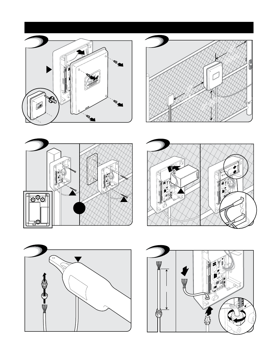
Control Box Installation
Remove control box cover.
15
A
1
Locate control box mounting area. IMPORTANT: Be sure to
mount box at least 3ft from AC power and 3ft off the ground.
3’ Min.
3’
Min.
4’
Max.
2
3
W
W
OR
Mount control box to post or fence using screws.
Position battery in control box as shown. Connect battery leads
from control board to battery. IMPORTANT: Red wire to (Red
Post) positive and black wire to (Black Post) negative.
15
RB500
12
Volt
/
7.0 A
mp M
oun
t
15
G
Black
Red
POS
NEG
4
1
15
FUSE
BA
TT+
BA
TT-
RE
CE
IV
ER
GT
O R
CV
R.
G
TO
LO
CK
A
U
X
RL
Y
PO
W
ER
IN
PU
TS
CO
N
TR
O
L
IN
PU
TS
M
A
ST
ER
C
A
B
LE
SL
AV
E
C
A
B
LE
CO
N
TR
O
L I
N
PU
TS
2
RE
CE
IV
ER
A
LM
GT
O R
CVR.
GRN
BLK
RED
SHADO
W
OPEN
EDGE
CL
OSE
EDGE
3
6
6”
B
5
Feed cable 6” into box. Tighten strain relief nut to secure cable.
Twist each end of the gate opener power cable’s 7 colored wires.
Feed cable through strain relief nut.
Control Box Installation