Lodar 20 Function FET Receiver with master output and IP Series Transmitter User Manual
Page 2
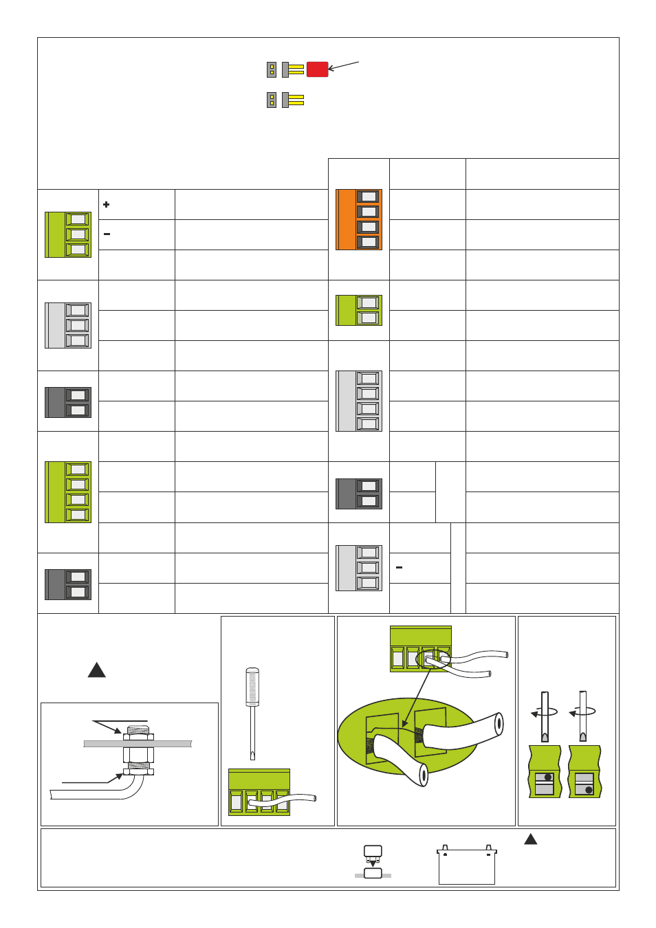
GROUND
12 / 24 VOLT
COMMON
FUNCTION 5
FUNCTION 6
FUNCTION 7
FUNCTION 8
MASTER
FUNCTION 1
FUNCTION 2
LK1
FUNCTION 3
FUNCTION 4
6
Make connections as detailed below
and record wire colours in the boxes
LK2
LK1, when bridged causes the Master Output to be Parallel
LK2, when bridged causes the Master Output to be Continuous
JUMPER MUST BE FITTED FOR LODAR TO WORK
POWER DOWN RECEIVER BEFORE MAKING CHANGES
JUMPER may be
or
RED
BLUE
S
T
O
P
Connections
S+ (Safety
Solenoid etc.)
L1 = LIMIT 1
L2 = LIMIT 2
L
IM
IT
IN
P
U
T
S
FUNCTION 9
FUNCTION 10
FUNCTION 15
FUNCTION 16
FUNCTION 17
FUNCTION 18
FUNCTION 11
FUNCTION 12
FUNCTION 13
FUNCTION 14
FUNCTION 19
FUNCTION 20
STOP
0 Volts
GROUND
7
FINAL CHECK
!
ALL ITEMS
IMPORTANT
Check all
connector
screws for
tightness
even the ones
that are not
used as these
could cause a
short circuit
if they vibrate
out of the
connector
Check locknut
Check gland
Check tightness of cable gland
a
b
Stray strands of wire can
cause a short circuit
c
d
CONNECTOR
BLOCK
secure wire
or Connect Battery
IT IS NOW SAFE TO RECONNECT THE POWER SUPPLY
Refit fuse
e
Fuse
Vehicle batteries contain gasses
w h i c h a r e f l a m m a b l e a n d
explosive. Wear eye protection
and do not lean over battery while
!
WARNING
SPECIAL
ORDER
ONLY
92220RX.01E