The power panel, Manikin setup – Laerdal SimMan Essential User Manual
Page 17
17
Manikin Setup
System Setup
Sim
ulation Setup
Clinical F
eatur
es
Maintenance
Tr
oubleshooting
Spar
e Par
ts
Manikin Setup
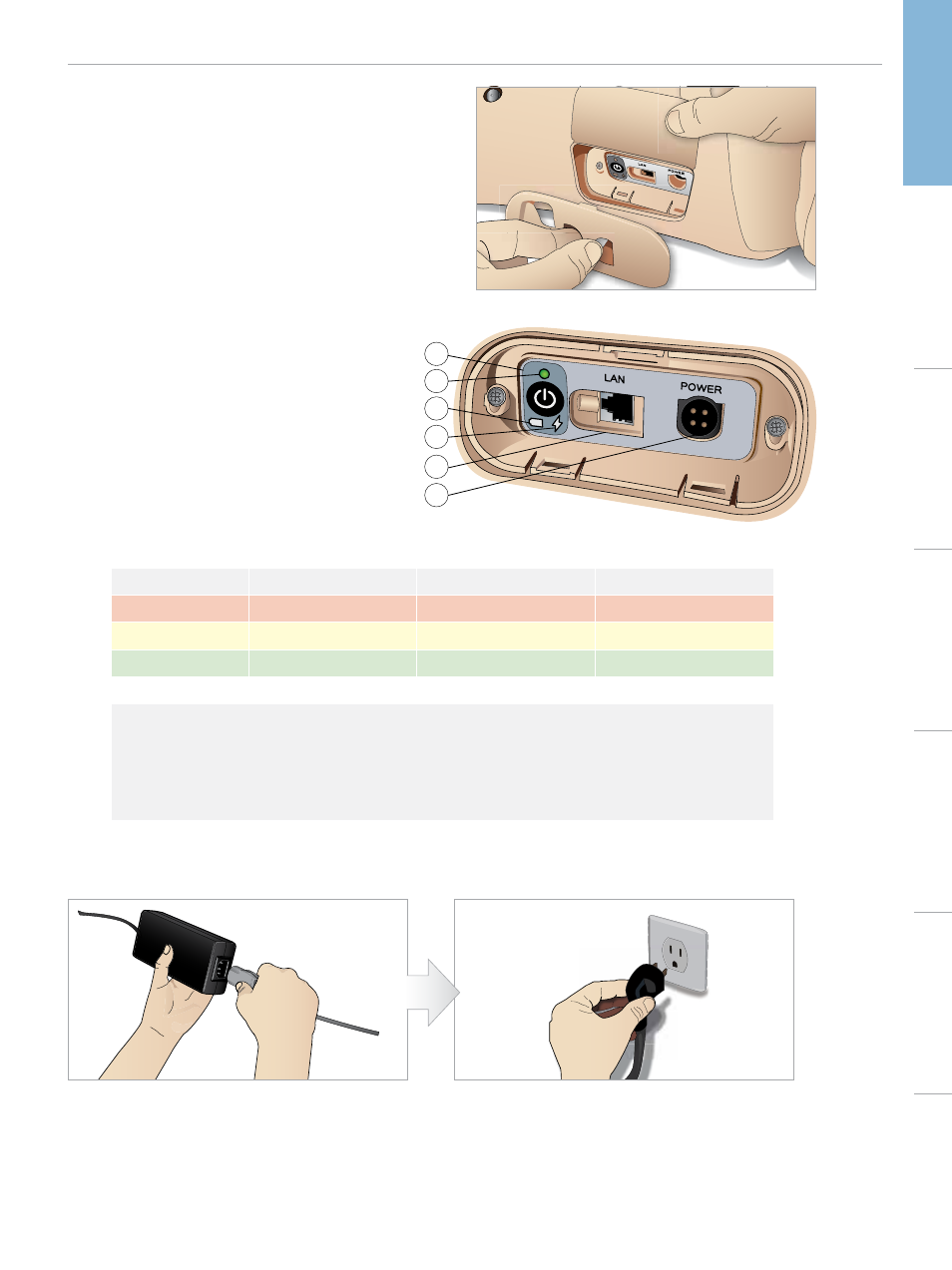
The Power Panel
The power panel is situated on the right side of the manikin, under
a loose skin flap. Lift the skin flap and pull out the protective cover.
To ensure easy access, use the zippered clothing provided with the
SimMan Essential manikin.
DC Input 9-24V X, XA
1
2
3
4
5
6
POWER PANEL OVERVIEW
1 Power ON / OFF button
2 Power status indicator
3 Battery status indicator
4 Charging status indicator
5 LAN network cable connector
6 External power supply connector
POWER PANEL LEDS DESCRIPTION
LED Color
Power Status
Battery Status
Charge Status
Red
Power Status*
0% - 20%
Not charging**
Yellow
Start up
20% - 70%
Charging
Green
Running
70% - 100%
Charge almost complete***
No light
Off
Off
No charge***
*
Blinking light
**
One or both batteries missing, overheated, damaged or otherwise not able to charge
***
Not recommended to charge the batteries too long
****
No power input, batteries are charged.
Power Save is activated when ever manikin is paused.
CHARGING THE BATTERIES INSIDE THE MANIKIN
1 Connect the manikin to the external power supply with
a power cord and plug that meets local specifications.
2 Plug the power supply into a wall outlet.