Chapter 6: interfaces, 1 dc power input terminal block, 2 safety ground studs for earthing – Dialogic SS7G21 User Manual
Page 35: 3 ac power input, 4 pcm interface ports, Interfaces, Dc power input terminal block, Safety ground studs for earthing, Ac power input, Pcm interface ports
35
Dialogic
®
SS7G21 and SS7G22 Signaling Servers Hardware Manual Issue 7
Chapter 6: Interfaces
This section provides connector pinout details for all used interface connectors on the SS7G21 and SS7G22.
For locations refer to
Section 5.3, “Back Panel” on page 33
6.1
DC Power Input Terminal Block
A DC Power Input Terminal Block is provided at the rear of the DC-input Power Supply Cage (DC products
only). Connection to a DC power source should be performed only by a qualified service tecnhician.
Details are therefore included in Part II of this manual, see
Section 9.2, “Power Supply Related Actions” on
. See also
6.2
Safety Ground Studs for Earthing
Two 8-32 UNC safety ground studs are provided for attachment of safety ground conductor to the product
when using the DC power supply option. Connection of the safety ground conductor should only be
performed by a qualified service tecnhician. Details are therefore included in Part II, see
“Safety Ground Studs, Conductor Installation” on page 51
.
6.3
AC Power Input
Two AC power input connectors, type IEC320, are provided at the rear of the Power Supply Cage of AC
powered product. Each connector supplies input power to one of the two Power Supply Module positions,
refer to
Section 5.3, “Back Panel” on page 33
for details. These connectors provide the safety ground
connections for the product.
When selecting a suitable power cord(s) for connection to the AC power input(s), ensure that the cords
comply with the AC POWER CORD warning provided in
Chapter 1, “Warnings and Cautions”
When selecting a suitable AC power outlet(s) for connection of the other end of the power cord(s), ensure
that the outlet is earthed, and that it complies with the IF AC POWER SUPPLIES ARE INSTALLED warning in
Chapter 1, “Warnings and Cautions”
which covers the following aspects; mains AC power disconnect,
grounding the rack installation, and overcurrent protection.
When in doubt, consult a qualified service tecnhician.
6.4
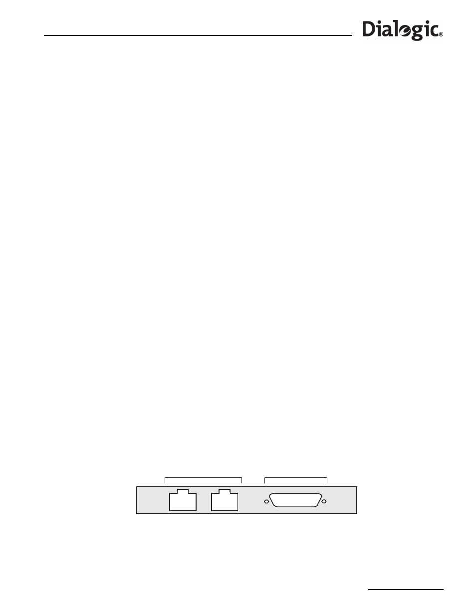
PCM Interface Ports
Each SS7 Signaling Board provides primary rate telecommunications (PCM) interfaces, each being
individually configured at run-time under software control to operate as balanced T1 or E1 ports, with
selectable line code and frame format. Depending on the type of SS7 Signaling Board(s) installed, there may
be two (
) or four (
) PCM interfaces per board. For information on setting the
port configurations, see the appropriate SS7G2x
lists the various user manuals.
Figure 5. PCM Ports on SPCI2S Boards
T 1 / E 1
P o r t s
V . 1 1
P o r t s
L4
L3
AUX