Labconco Pressure Controller User Manual
Page 18
Labconco Operating Instructions 5242600, Rev. B 4/27/07, ECO E275
18 of 20
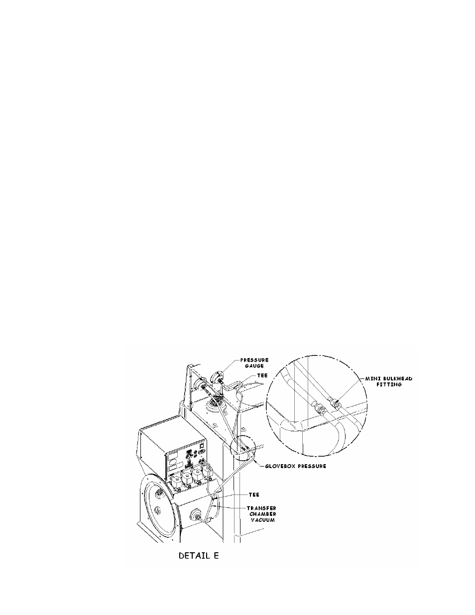
2. Bulkhead Fitting
a. Locate the brass mini bulkhead fitting in your kit and install the fitting at the
opening provided on the back wall of the glove box wrapper (see Detail E).
3. Glove Box Pressure
a. Locate the line that comes from the pressure gauge (see Detail E ) to the
fitting installed at the top of your glove box. This gauge is labeled on the front
panel and is the one on your right when looking at the back of the front panel
(see Detail E). This line is also a contaminated line on existing glove boxes
and the appropriate precautions should be taken.
b. Make a cut in the line about halfway between the gauge and the fitting. Join
the cut lengths together with the brass tee that came with you kit.
c. Measure and cut a length of the 3/32 ID polyvinyl tubing (the smaller of the
tubing) and connect the spliced tee to the mini bulkhead fitting on the back of
the Glove Box wrapper.
d. Again, measure and cut a length of the same tubing and connect it between the
mini bulkhead fitting on the glove box wrapper and the port labeled “Glove
Box Pressure” on the back of the Pressure Controller (see Detail E).
4. Transfer Chamber Vacuum
a. Locate the existing line that comes from the back of your glove box wrapper
to the transfer chamber fitting (see Detail E).
b. Make a cut in the line at a point near or within 12 inches of the transfer
chamber fitting and join the line together with a brass tee that came with your
kit.
c. Measure and cut a length of the 3/32 ID polyvinyl tubing (the smaller of the
tubing) and connect the spliced tee to the port labeled “Transfer Chamber
Vacuum” on the back of he Pressure Controller (see Detail E).