Quick guide overview, Quick guide overview 8, 1 front panel overview – Lab.gruppen C Series 5:4X User Manual
Page 15: 1 power on/off and remote switch, Figure 5.1: c series front panel layout
C Series C 20:8X, C 10:8X, C 10:4X and C 5:4X Operation Manual rev. 1.1.4
Quick Guide Overview
8
4. Quick Guide Overview
4.1 Front panel overview
ON/OFF
C10:8X
REMOTE
C SERIES
LABEL AREA
TEMP
VHF
CPL
VPL | CLIP
SIG | HI-IMP
TEMP
VHF
CPL
VPL | CLIP
SIG | HI-IMP
CH|
A CH|B
CH|
C CH|D
CH|
E CH|F
CH|
G CH|H
MUTE
FAULT
MUTE
FAULT
MUTE
FAULT
MUTE
FAULT
POWER
BRIDGE
BRIDGE
BRIDGE
BRIDGE
PAL
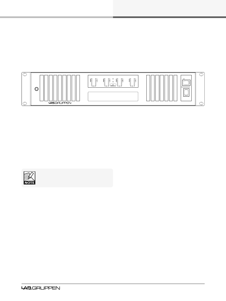
Figure 5.1: C Series front panel layout
The amplifier’s front panel presents the performance and fault condition indicators, power and remote switch-
es, and a removable dust-filter cover. Four level potentiometers located behind the cover provide individual
attenuation for the four amplifier channels. Range is 0 dB to - infinity. The 12 o’clock position indicates -10 dB
attenuation. A label area is located beneath the LED display.
To remove the dust-filter cover, loosen the thumbscrew at the far left. This allows removal of the dust-filters
for cleaning, and provides access to channel attenuation. The front cover may be made “tamper resistant” by
replacing the thumbscrew with a Philips head or safety Torx screw. Thread size is M3.
4.1.1
Power on/off and remote switch
The Power ON/OFF switch is located on the right side. A second switch, labeled “REMOTE,” is located above
the Power switch. When the Remote switch is on, (with the mains connected and power switch turned on)
the yellow LED above it will illuminate indicating that external power ON/OFF commands from the NomadLink
network connection will switch the amplifier on or off. When Remote is activated the amplifier will not switch on
until a “Power On” command is received from the network. When the remote switch is off, it is not possible to
switch amplifier power on or off using NomadLink network control.
Never operate the amplifier without the dust -filters in
place.