Neon-ss fm, Optional version – HITEC Neon SS User Manual
Page 8
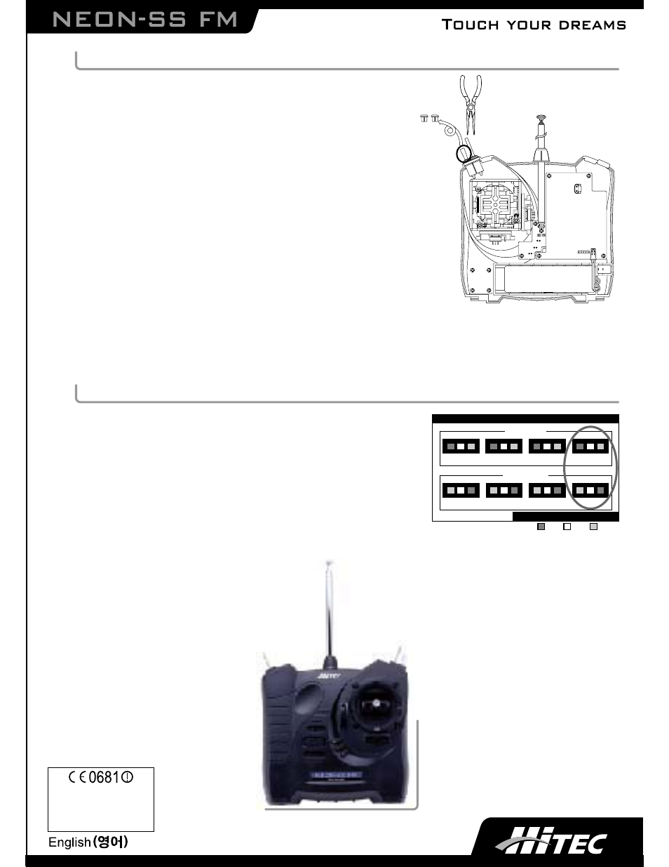
Dual Rate Switch Installation
Note: ATV board component must be installed prior to adding the
Dual Rate Switch.
1. Open the case as instructed on page 3 and disconnect the throttle
switch harness plug from the main board.
2. Disconnect the power from the radio by removing the battery holder or
unplugging and removing the Nicad battery pack.
3. Remove the four screws on the front of the radio that hold the gimbal in.
4. Remove the plug in the hole marked, D/R
5. Slide the Dual Rate Switch into the hole and secure with the lock nut.
6. Reinstall the gimbal.
7. Route the wire and attach the white connector into the plug marked
DR S/W on the large brown PC board.
8. Re-install the battery.
9. Plug the throttle back in.
10. Taking care not to pinch any wires, slide the top of the case half's together then snap the bottom together.
Reinstall the antenna, antenna bezel, crystal and the lower case tabs.
11. All done? Range check your radio and go fly!
4th Channel Three Position Switch Accessory Installation
1. Open the case as instructed on page 3 and disconnect the throttle
switch harness plug from the main board.
2. Disconnect the power from the radio by removing the battery holder
or unplugging and removing the Nicad battery pack.
3. Remove the plug in the hole marked, AUX.
4. Slide the Switch into the hole and secure with the lock nut.
5. Route the wire and attach the connector into the plug marked CH-4
on the large brown PC board.
6. Re-install the battery.
7. Plug the throttle back in.
8. Taking care not to pinch any wires, slide the top of the case half's together then snap the bottom together.
Reinstall the antenna, antenna bezel, crystal and the lower case tabs.
9. All done? Range check your radio and go fly!
Austria, Belgium, Denmark, Finland,
France, Germany, Greece, Iceland,
Ireland, The Netherland, Italy, Spain,
Norway, Portugal, United Kingdom,
Luxembourg, Sweden, Switzerland
NEON-SS FM
optional version
www.hitecrcd.com
Dual rate switch
CH1
CH2
CH3
CH4
CH1
CH2
CH3
CH4
NORMAL
REVERSE
Colors denote connector wire colors
SERVO REVERSE
G
G
Y
O
G
Y
O
G
Y
O
G
Y
O
Y
O
G
Y
O
G
Y
O
G
Y
O
G
Y
O
Green
Yellow
Orange