Heath Consultants EyeCGas User Manual
Page 13
EYE-C-GAS user's manual
Page 13
P/N PS8G9006-Rev 1
www.heathus.com
www.opgal.com
5
EYE-C-GAS Controls and Operation
The following section details operation and use of the EYE-C-GAS Infrared Camera.
5.1
Controls and Display
Using the EYE-C-GAS is simple and intuitive. Large, convenient buttons located on the top of
the EYE-C-GAS control most camera operations. The two connectors located on the front panel
facilitate connection to external devices.
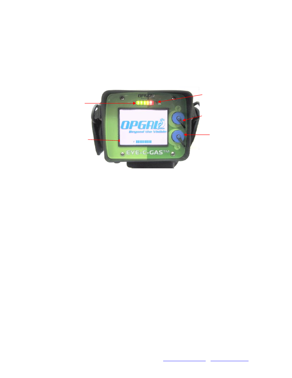
5.1.1 Front Panel
The front panel of the EYE-C-GAS comprises the following:
5.1.1.1 3.5" Color LCD Display
A VGA format 640 x 480 LCD displays high resolution grayscale infrared and visible color video
images. The glare resistant LCD is designed to be viewable in brightly lit areas.
5.1.1.2 Battery Status LEDs
Five LEDs, from left to right, display EYE-C-GAS battery status. The three green, one yellow
and one red LEDs provide easy recognition of remaining battery capacity. The LEDs will
extinguish in order from left green to right red. A single red LED indicates the battery is very
low and should be changed out with a fully charged one.
5.1.1.3 Camera Warning Indicator
A red LED on the right side of the row of LEDs indicates when the EYE-C-GAS or battery is not
working properly.
5.1.1.4 USB2 Connector
The USB2 connector is useful at the conclusion of field operations, allowing a user to upload
information to EYE-C-GAS as well as download audio and video files directly to a PC. This
connector is protected by a cover which must be in place when the connector is not in use.
5.1.1.5 Accessories Connector
The accessories connector allows a user to connect the standard head set and optional analog
video adaptor. This connector is protected by a cover which must be in place when the
connector is not in use.
Figure 1: Front Panel
Battery Status LEDs
3.5" Color LCD
USB2
Connector
Accessories
Connector
Warning Indicator