38 installation, Installation procedures – Hatteland Display 26 inch - HD 26T21 MMD (Widescreen, Touch Screen) User Manual
Page 38
38
Installation
IND100078-33
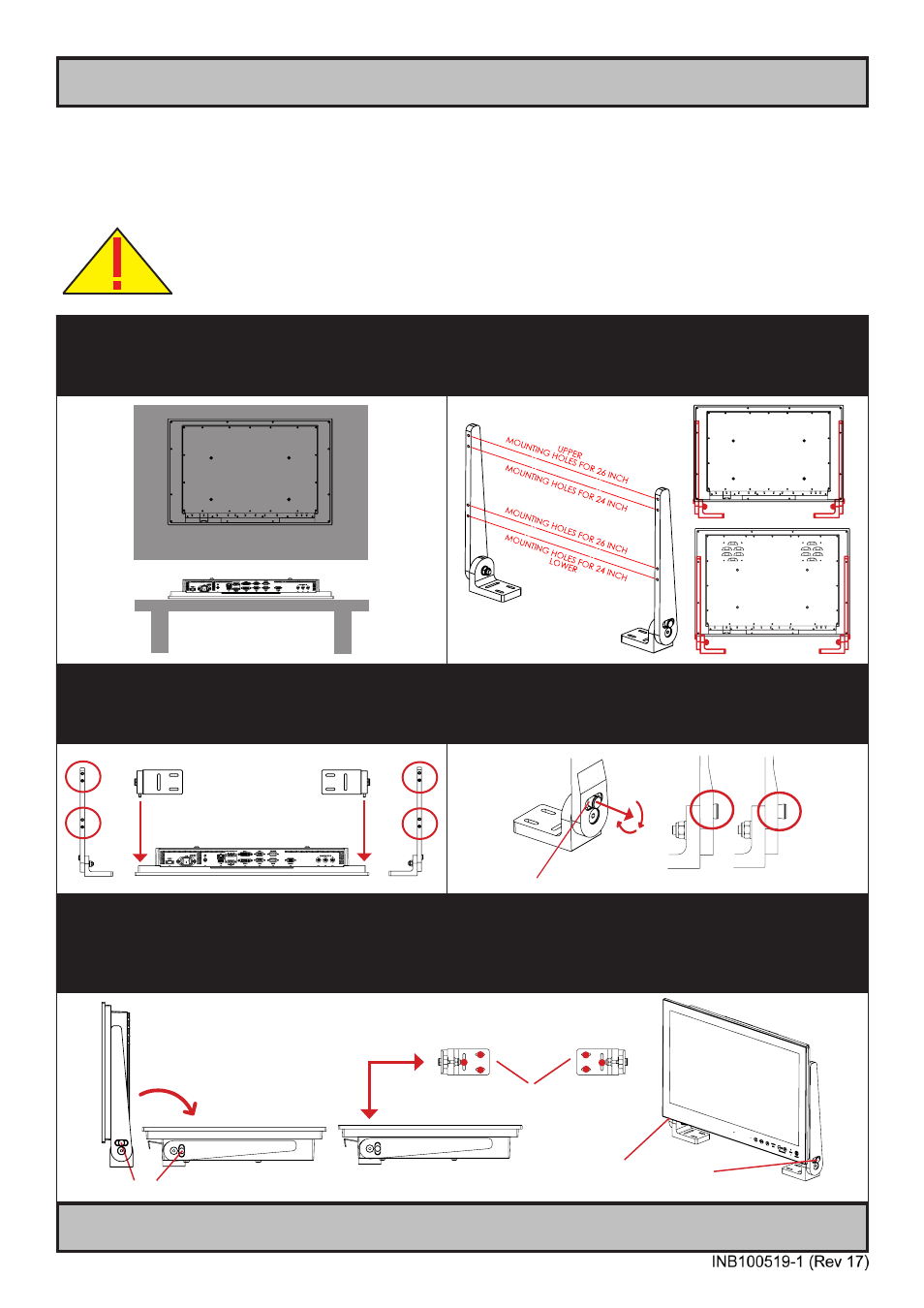
Installation Procedures
Mounting Bracket for Table / Desktop installation - 24”,26”
You need: M5 Unbrako® Hex Key tool and 1 pcs of HD TMB SX1-C1 Mounting Bracket Kit.
Fasteners (6 pcs M6) for Table / Desktop location not included. Procedure suitable for: Display and Panel Computers.
Attention: A suitable pre-drilled location and knowledge of measurements for both main unit and
brackets/tilting functionality should be prepared and checked prior to mounting. Please disconnect
ALL cables before proceeding. Please review User Manual or visit www.hatteland-display.com for
Technical Drawings regarding measurements for both main unit and Mounting Brackets.
1: Place the unit on a dry, flat, clean, soft surface (i.e.
table) with the glass front facing down as illustrated.
Connector area should be facing downwards from you.
2: Inspect the mounting holes of brackets. For mounting to
a 24 inch unit, please use the
lower holes as indicated.
For mounting to a 26 inch unit, please use the
upper holes
as indicated.
Seen from
above
Connector Area
24 inch
26 inch
3: Place one bracket at the time with the mounting
holes facing down into the suitable mounting
position and fasten with 2 x M5 screws on each
bracket. Torque Force 3.5Nm.
4: While unit is lying flat on table, check the Tilting Lock
Pin position. These can be pulled out by hand, turned 90°
(FIG1) and turned back 90° until the Lock Pin automatically
clicks into place by a spring (FIG2).
FIG1
FIG2
FIG2
FIG1
FIG2
Locked Unlocked
5: You may now mount the unit onto your desired location. It is advised that you unlock the Lock Pin (as shown in
step 4), tilt the unit 90° backwards (FIG1) and properly fasten the bracket base into location (FIG2).
NB! Be careful not to break or scratch the edge of the front glass! Then repeat step 4 again until your desired
tilting position has been achieved and you have verified that the Lock Pin are in locking position and the unit is firmly
attached and does not appear loose (FIG3).
Unlock, tilt and lock
FIG1
FIG2
Top View
Use appropriate fasteners
6 pcs x M6 needed
FIG3
Re-check Lock Pins!