Hanna Instruments HI 21 Series User Manual
Page 12
23
22
FS•O = NC (Normally Closed)
De-energized Relay
COM
FS•C = NO (Normally Open)
Energized Relay
ALARM RELAY
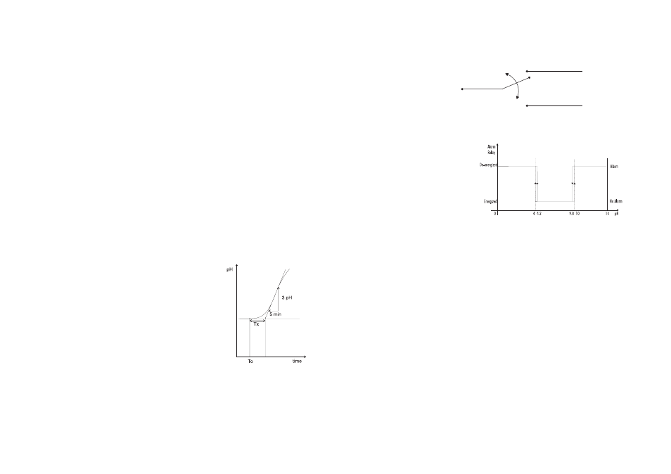
The alarm relay functions in the following manner:
During alarm condition, the relay is de-energized. When not
in alarm condition, the relay is energized.
Example:
High alarm set at 10 pH
Low alarm set at 4 pH
An hysteresis will eliminate the possibility of continuous se-
quences ‘energizing/de-energizing’ of the alarm relay when
the measured value is close to the alarm setpoint. The hyster-
esis amplitude is 0.2 pH in HI 21 and 30 mV in HI 22.
Moreover the alarm signal is generated only after a user se-
lectable time period (alarm mask) has elapsed since the
controlled value has overtaken one alarm threshold. This
additional feature will avoid fake or temporary alarm condi-
tions.
Note
If the power supply is interrupted, the relay is de-energized as
if in alarm condition to alert the operator.
In addition to the user-selectable alarm relays, all HI 21 and
HI 22 models are equipped with the Fail Safe alarm fea-
ture.
The Fail Safe feature protects the process against critical
errors arising from power interruptions, surges and human
errors. This sophisticated yet easy-to-use system resolves these
predicaments on two fronts: hardware and software. To elimi-
nate problems of blackout and line failure, the alarm function
operates in a “Normally Closed” state and hence alarm is
triggered if the wires are tripped, or when the power is down.
1. Starting from a solution with a pH or mV value different
from the dosed liquid (at least a 3 pH or 150 mV differ-
ence) turn on the dosing device at its maximum capacity
without the controller in the loop (open loop process). Note
the starting time.
2. After some delay the pH or mV starts to vary. After more
delay, the pH or mV will reach a maximum rate of change
(slope). Note the time that this maximum slope occurs and
the pH or mV value at which it occurs. Note the maximum
slope in pH or mV per minute. Turn the system power off.
3. On the chart draw a tangent to the maximum slope point until
intersection with the horizontal line corresponding to the initial
pH or mV value. Read the system time delay Tx on the time axis.
4. The deviation, Ti and Td can be calculated from the following:
• Deviation = Tx * max. slope (pH or mV)
• Ti = Tx / 0.4 (minutes)
• Td = Tx * 0.4 (minutes).
5. Set the above parameters and restart the system with the
controller in the loop. If the response has too much over-
shoot or is oscillating, then the system can be fine-tuned
slightly increasing or decreasing the PID parameters one
at a time.
Example:
the chart recording in the figure
aside was obtained continuously
dosing an alkaline solution to a
weak acid solution in a tank. The
initial settings will be:
Max. slope = 3 pH/5 mins = 0.6
pH/min
Time delay = Tx = approx. 7 mins
Deviation = Tx * 0.6 = 4.2 pH
Ti = Tx / 0.4 = 17.5 mins
Td = Tx * 0.4 = 2.8 mins