Hanna Instruments HI 8614 User Manual
Page 9
17
16
FOR HI 8615L ONLY
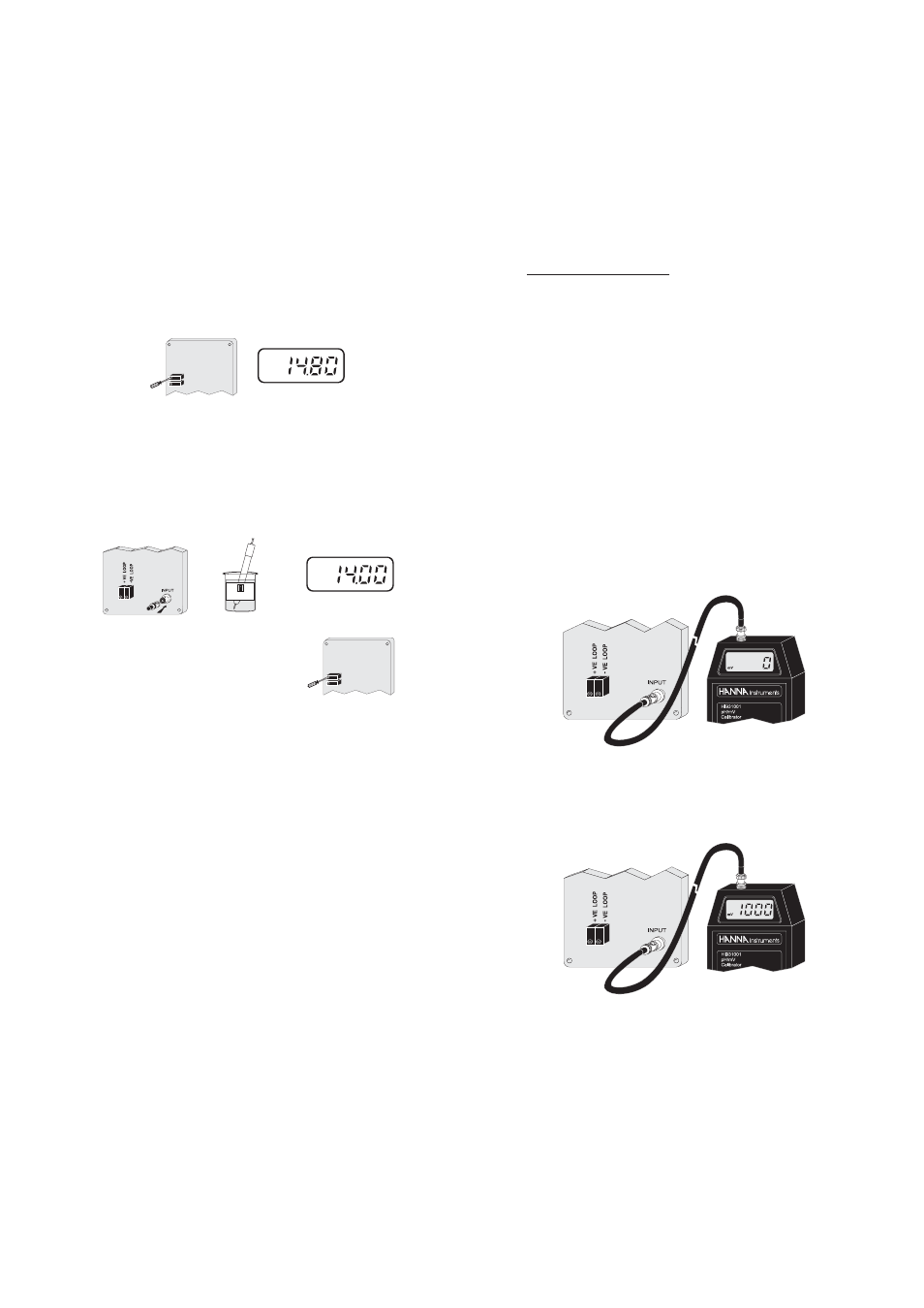
The HI 8615L is factory calibrated, and the
displayed values are referenced to the 4-20
mA loop current (e.g. LCD displays -1000
mV when loop current is 4.00 mA and dis-
plays +1000 mV when current is 20.00 mA).
Under normal application, adjustment on this
module may not be necessary. If routine
check is required, the following procedures
shall be performed.
•
Follow the above procedure for HI 8615
(see page 12).
•
Simulate a 12.00 mA loop current for the
transmitter (i.e. 0 mV at Electrode input)
and check display reading.
•
Simulate a 20.00 mA loop current for the
transmitter (e.g. +1000 mV at Electrode
input) and check display reading.
•
Set the simulator to 350 mV and adjust
the slope trimmer to read 14.8 mA on the
ammeter or 350 mV on the HI 8615L
display (HI 8615L only).
•
Connect the ORP electrode to the module
and immerse the tip of the electrode into
the beaker of HI 7020 ORP solution and
check that the ammeter reading lies be-
tween 13.6 and 14.2 mA or the instrument
reading is between 200 and 275 mV at
25°C (HI 8615L only).
•
Only if the reading lies out-
side this range, adjust the
slope adjustment trimmer on
the transmitter to reflect a
reading within this range.
SLOPE ADJUSTMENT
OFFSET ADJUSTMENT
mA
mA
HI 7020
SLOPE ADJUSTMENT
OFFSET ADJUSTMENT