Hanna Instruments HI 8614 User Manual
Page 4
7
6
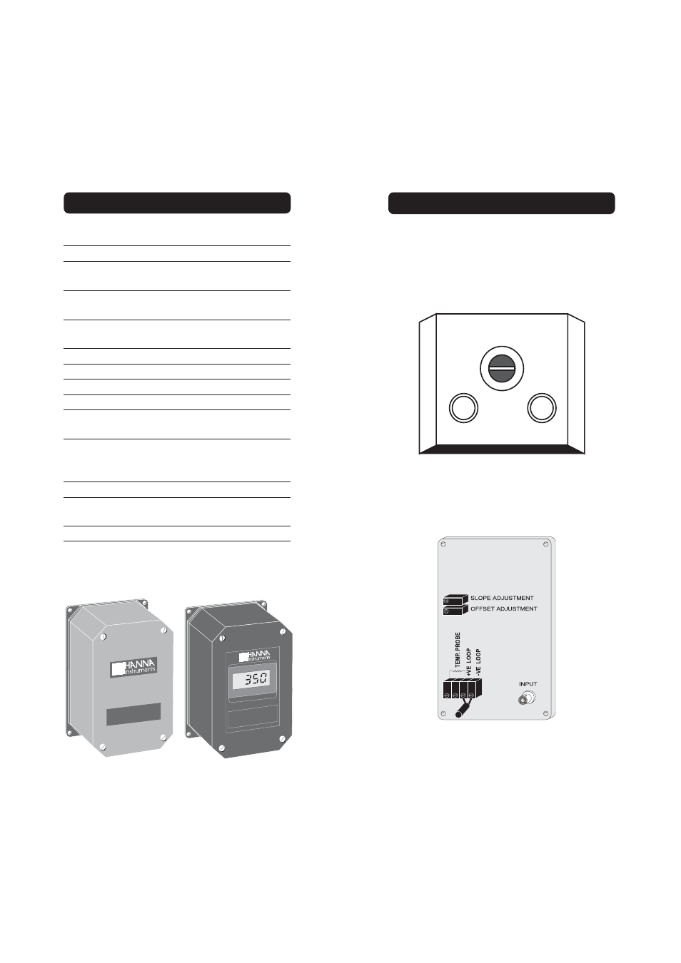
TERMINAL BOARD CONNECTIONS
Unscrew the 4 screws and remove the top cover.
There are three cable glands on the transmitter
cover. The large cable gland with the split in the
rubber is for the electrode.
ELECTRODE
CABLE GLAND
WIRE CABLE GLANDS
Connect the positive supply to the strip terminal
"+VE LOOP" and the negative supply to the
terminal "-VE LOOP" of the transmitter terminal
block.
SPECIFICATIONS OF HI8615 & HI8615L
HI 8615
ORP TRANSMITTER
mV
HI 8615
ORP TRANSMITTER
Range
4 to 20 mA / ±1000 mV
Resolution
0.01 mA / 1 mV
Accuracy (@20°C/68°F)
±0.02 mA / ±5 mV
Typical EMC Deviation
±0.25 mA / ±15 mV
Calibration
Offset: ±0.8 mA / ±100 mV
Slope: ±0.8 mA / 90 to 110%
Input Impedance
10
12
Ohm
Output
4-20 mA (isolated)
Installation Category
I I
Protection
IP 65
Environment
0 to 50°C (32 to 122°F);
RH max 95% non-condensing
Power Supply
HI8615: 18 to 30 Vdc
HI8615L: 20 to 36 Vdc
Load
Max 500 Ohm
Dimensions
165 x 110 x 90 mm
(6.5 x 4.3 x 3.5'')
Weight
1 kg (2.2 lb.)