Hanna Instruments HI 8614 User Manual
Page 8
15
14
SLOPE ADJUSTMENT
OFFSET ADJUSTMENT
•
If the reading lies outside
this range, adjust the slope
adjustment trimmer on the
transmitter for a reading just
within this range.
The unit is now calibrated.
A complete calibration of the transmitter mod-
ule is advised periodically.
This calibration procedure requires the HI 8427
or the HI 931001 pH and ORP simulator to
simulate the ORP electrode.
HI 8427 or HI 931001 produce a known signal
into the system so that the faults of the
system can be isolated.
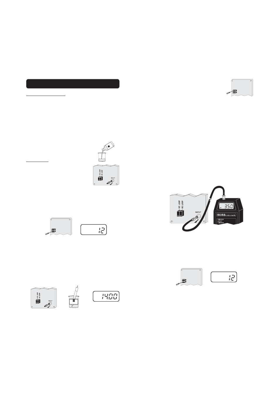
•
Connect the ORP transmitter to the simu-
lator.
•
Set the simulator to 0 mV and adjust the
offset trimmer to read 12 mA on the am-
meter or 0 mV on the HI 8615L display (HI
8615L only).
SLOPE ADJUSTMENT
OFFSET ADJUSTMENT
mA
ORP CALIBRATION (HI8615 & HI8615L)
Initial preparation
Disconnect the +ve supply cable from the
"+VE LOOP" terminal and connect a 20 mA
f.s. ammeter between the +ve cable and the
"+VE LOOP" terminal. With HI 8615L the
instrument display can be used during cali-
bration without the need to connect the am-
meter. In this case the values are directly
expressed in mV units.
Pour a small quantity of HI 7020
ORP solution into a beaker.
Procedure
•
Connect the shorting BNC
connector to the ORP trans-
mitter.
•
Adjust the OFFSET AD-
JUSTMENT trimmer on the module for a
display of 12 mA on the ammeter or 0 mV
on the instrument display (HI 8615L only).
This sets the zero point for the transmit-
ter.
•
Connect the ORP electrode to the transmit-
ter and immerse the tip of the electrode
into a beaker of HI 7020 ORP calibration
solution, and check that the ammeter read-
ing lies between 13.6 and 14.2 mA or the
instrument reading is between 200 and 275
mV at 25°C (HI 8615L).
HI 7020
mA
SLOPE ADJUSTMENT
OFFSET ADJUSTMENT
mA
HI 7020