Functional diagram hi 9912, Front panel – Hanna Instruments HI 9912 User Manual
Page 6
6
FUNCTIONAL DIAGRAM HI 9912
FUNCTIONAL DIAGRAM HI 9912
FUNCTIONAL DIAGRAM HI 9912
FUNCTIONAL DIAGRAM HI 9912
FUNCTIONAL DIAGRAM HI 9912
pH
0
1
2
0
100
200
mV
ALARM
pH
0
SECONDS
mV
200
0
TIMER
MINUTES
90
PROPORTIONAL SETTINGS
1
10
2.5
5
7.5
0
SECONDS
pH
2.0
0
TIMER
MINUTES
90
PROPORTIONAL SETTINGS
1
10
2.5
5
7.5
500
900
CAL
ALARM
ON
OFF
SET
FEED
mV
OFFSET
SLOPE
ALARM
ON
OFF
0.5
1.5
pH
HI 9912
mV
ORP
ALARM
8
SET
FEED
ALARM
6
7
ACID
OXID
700
50
150
SET pH
SET ORP
ALARM
LINE
1
3
4
5
6
7
8
9
10
11
12
14
13
15
16
17
18
19
20
21
2
2
4
8
22
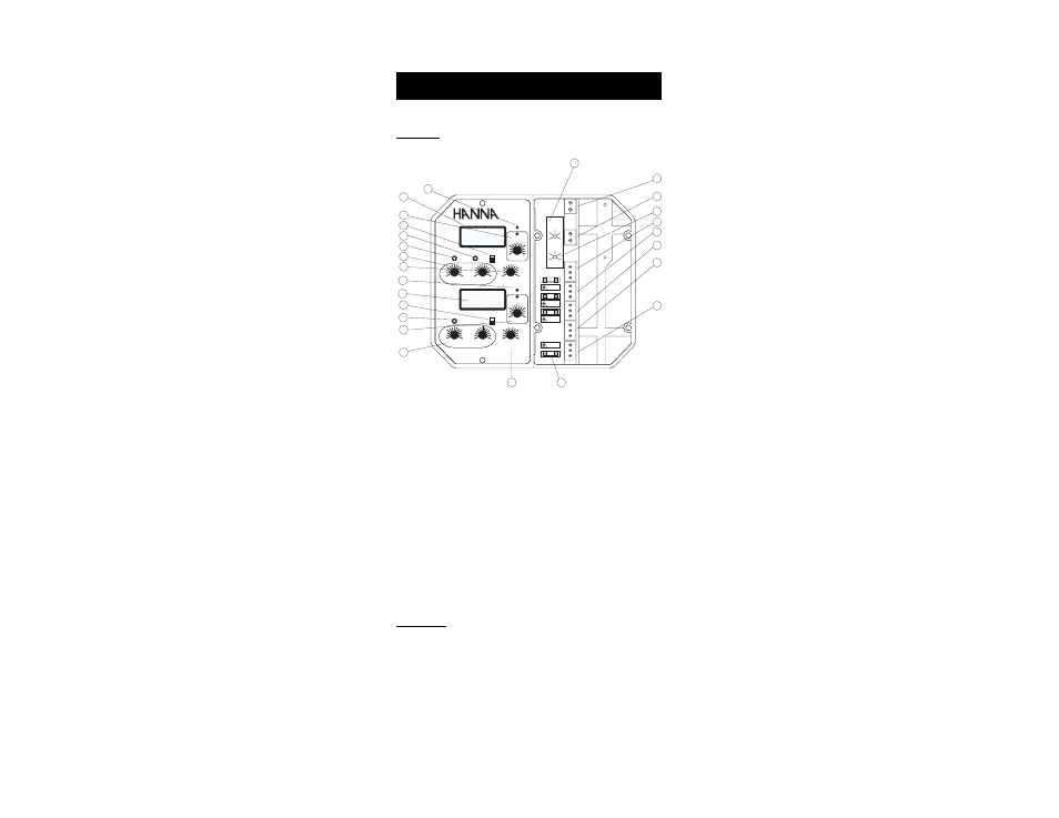
FRONT PANEL
Left panel
1. Alarm LED signal for pH
2. Liquid Crystal Displays for pH and ORP
3. Acid feed LED and dial to adjust the pH setpoint
4. Alarm disable switches for pH and ORP
5. Slope calibration trimmer for pH
6. Offset calibration trimmer for pH
7. Proportional pH band and time cycle settings
8. Two independent maximum dosage timers
9. Alarm LED for mV (ORP)
10. Calibration trimmer for mV
11. Oxidant feed LED and dial to adjust the ORP setpoint
12. Proportional mV band and time cycle settings
Right panel
13. pH alarm setting from 0 to 2 pH
14. Short the terminals if a pH ground probe is not in use, or
connect the ground probe wire to the Matching Pin terminal
15. Short the terminals if an ORP ground probe is not in use, or
connect the ground probe wire to the Matching Pin terminal
16. ORP alarm setting from 0 to 200 mV