Hanna Instruments HI 9912 User Manual
Page 12
12
Make sure that the controller has been properly calibrated before
commencing and that the pH and ORP setpoint(s) have been
adjusted (see the following pages).
The pH and ORP electrodes and any ground probes must be properly
connected and wired to the controller (see preceding pages).
Remove the protecteive caps if they are still on the tip of the electrodes
and ensure that the electrodes are immersed in the solution (at least
4cm/1.5”). The electrodes should be in-
stalled in such a away that they
permanently lie in the solution whether in
a well, tank or on the discharge pipe.
The actual pH and ORP values will be
displayed on the LCD’s.
NORMAL OPERATION &
NORMAL OPERATION &
NORMAL OPERATION &
NORMAL OPERATION &
NORMAL OPERATION &
MEASUREMENT
MEASUREMENT
MEASUREMENT
MEASUREMENT
MEASUREMENT
8.00
650
pH
mV
ORP
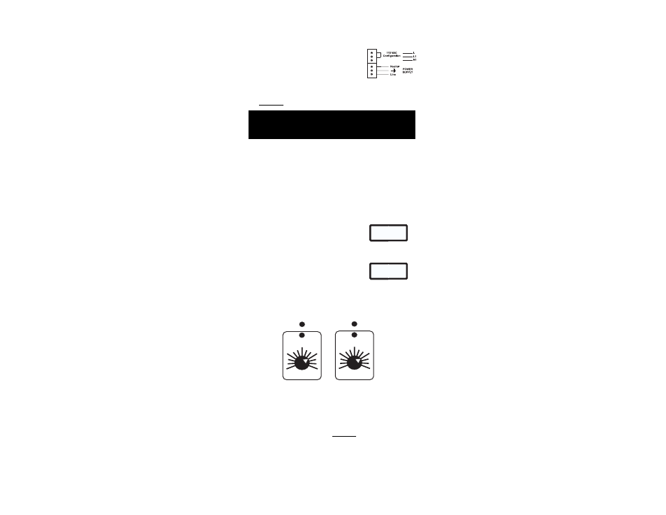
HI 9912 provides for visual dosing status through two LED’s, one for
pH and another for ORP. The LED’s light up when the controller is in
the pH or ORP dosage mode and the terminals are activated.
500
900
SET
FEED
mV
ALARM
OXID
700
pH
ALARM
8
SET
FEED
6
7
ACID
• For 110-115V, short the L and L1 termi-
nals. Then wire the external power supply
to the three terminals as shown.
• Replace the cover with the gasket and
screw it tight with the 4 screws provided.
Only then
Only then
Only then
Only then
Only then
connect the controller to the mains.
NOTE:
HI 9912 provides for two separate relays, one for pH and another for
ORP. In order to save on chemicals and due to the slow reaction of
oxidants, the controller incorporates a Consent feature
Consent feature
Consent feature
Consent feature
Consent feature by which
ORP measurements are adjusted only after pH has been corrected.
The Consent feature makes the pH correction
pH correction
pH correction
pH correction
pH correction the master
master
master
master
master and the
ORP adjustment
ORP adjustment
ORP adjustment
ORP adjustment
ORP adjustment the salve
salve
salve
salve
salve for a better control.