0 installation – Hall Research VSA-31 User Manual
Page 5
A / V Switch-Cat
TM
5
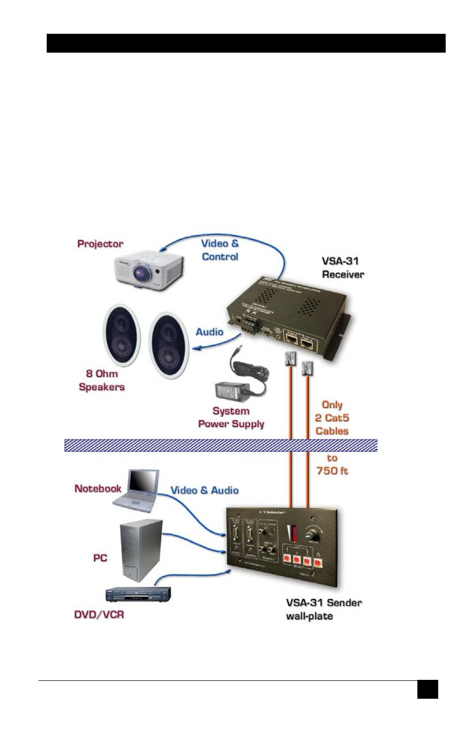
3.0 Installation
In a typical installation, the Sender unit is located on a wall or panel and
is wired to the remote Receiver unit via 2 Cat5 cables.
The sender qualifies as a low-voltage class 2 device and does not require
a J-box. In fact it does not even need a power supply to be connected to it,
as it draws power via the signal connection to the remote unit. However,
in most instances it is easier to use a standard 4-gang electrical box in
order to attach the faceplate to the mounting surface or structure.
Please contact HRT or your desired electrical supply house for purchasing
the J-box. These are generally inexpensive units.
See also other documents in the category Hall Research Accessories communication:
- 1800-RA (4 pages)
- 400-DX (2 pages)
- 511-POH-17W (12 pages)
- 200 (4 pages)
- 97-P (20 pages)
- CP200 (4 pages)
- CVA-2000 (7 pages)
- DVC-3 (16 pages)
- EM-EDID-HD15 (2 pages)
- EMX-DVI (12 pages)
- EMX-HD-AUD (12 pages)
- EX-HDMI-2A (2 pages)
- HD-AUD (5 pages)
- HR-731 (13 pages)
- U2-160 (8 pages)
- U2-160-DP (8 pages)
- UH-1BT (12 pages)
- UH-1C (8 pages)
- UH-1D (8 pages)
- UH-2C (8 pages)
- UH-2C-3S (12 pages)
- UH-2D (8 pages)
- UHBX-3S (12 pages)
- UHBX-3S (13 pages)
- UHBX-4X (7 pages)
- UHBX-4X (20 pages)
- UHBX-4X (8 pages)
- UHBX-4X (3 pages)
- UHBX-P1 (12 pages)
- UHBX-SW3 (12 pages)
- UHBX-SW3 (20 pages)
- UHBX-SW3 (3 pages)
- UR232 (16 pages)
- URA (20 pages)
- URA-232 (32 pages)
- URA-RS232-C (12 pages)
- USB3-EXT-16 (4 pages)
- UU-2X4 (12 pages)
- UV1 (16 pages)
- UV1-R (12 pages)
- UV1-S-16X (16 pages)
- UV232-16X (16 pages)
- UV232A (12 pages)
- UVA-DP (20 pages)
- UVB1-CP (4 pages)