Projector controller w/ built-n vga splitter – Hall Research HR-3P User Manual
Page 10
Projector Controller w/ Built-n VGA Splitter
10
NOTE
The discrete I/O is not designed to source or sink much current.
The input is pulled up by a 4.7K resistor. You can short the input to ground
or open it (contact closure operation) You can also apply a voltage to this
pin from 0 to 12 v max (a diode is provided to block current flow into the
unit) any input higher than 1.5v is considered to be logic high and an input
less than 0.5v is considered logic low. Make sure that this pin does not go
negative, as a below zero voltage at this pin can damage the device.
The discrete output is directly driven from a CMOS source that can sink 25
mA, and source about 1 mA when high. We recommend that you use an
external optical isolator or transistor to isolate and buffer this output from
any external circuit that you may want to use it with.
You should not pull the discrete output above 5v or below ground. You can
operate a 5 volt relay with it or use a transistor or optical isolator to control
higher loads.
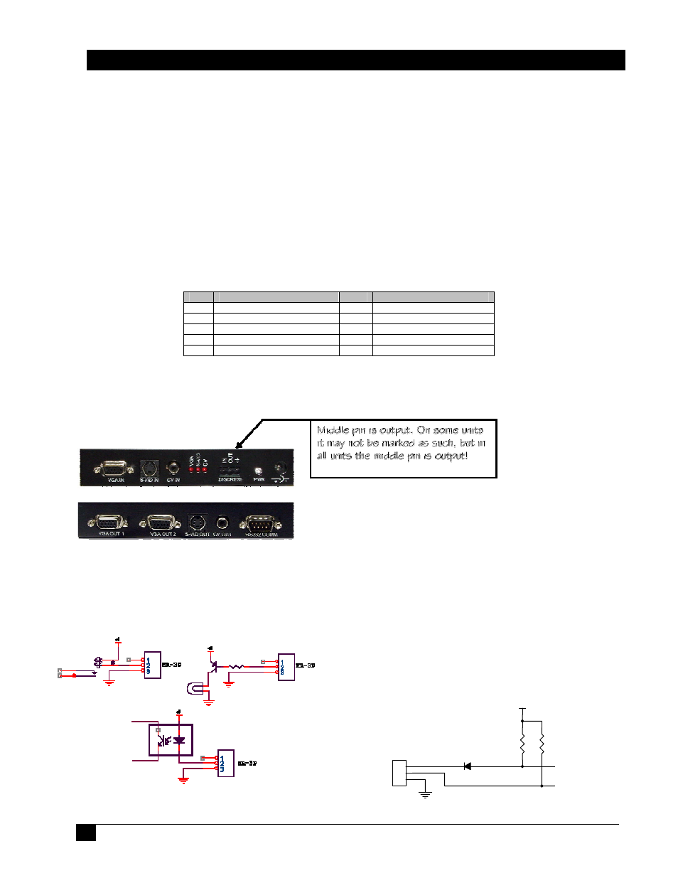
Figure 3 – Internal Circuit of
DISCRETE IN/OUT
+5V
DISCOUT
DISCIN
4.
7K
J9
3 POS TERM BLOCK
1
2
3
4.
7K
DTEs talk directly to DCEs. If you have 2 DTEs trying to talk, they need a
crossover serial cable connecting them. In the same way if you have 2 DCEs
trying to talk, they will need a crossover serial cable connecting them as well.
Generally DTEs will have a male DB9 connector and DCEs will have a female
DB9 connector. You will notice that the serial cable included with the HR-3P has
a female DB9 connector on both ends. This is a crossover serial cable. This cable
is required to connect the HR-3P to the PC to upload the strings. Because the
HR-3P has a Male DB0 connector, this indicates that the HR-3P is a DTE, which
is why it requires a crossover serial cable to connect to a computer/PC serial
port. When you are done uploading the strings to the HR-3P, you will need to
use a crossover or straight through serial cable to connect the HR-3P to your
serial device depending on what type of serial device you are trying to control.
Here is the pinout of the HR-3P. The pinout of the DB9 male connector on the
HR-3P is as follows:
Connect the discrete input and output to the appropriate switches; connect the necessary
video inputs and outputs to the correct ports on the HR-3P and power on the HR-3P. The
HR-3P is now scanning for active video signals and change in the discrete input.
Pin
Function
Pin
Function
1
Not Used
6
Not Used
2
Receive (input)
7
RTS (output, pulled high)
3
Transmit (output)
8
Not Used
4
DTR (output, pulled high)
9
Not Used
5 Ground