Installation, 8 electrical connections, 9 commissioning – Glow-worm Clearly Hybrid - Compact Hydraulic Module HB User Manual
Page 11: 10 specific adjustment
0020096881_02 - 08/10 - Glow-worm
- 9 -
INSTALLATION
8 Electrical connections
e
Incorrect installation can cause electric shock or
appliance damage. The electrical connection of
the appliance must be made only by a qualified
engineer.
The external wiring must be earthed, with correct polarity and in
accordance with current standards.
The manufacturer declines any responsibility for damages to
persons or others caused by the incorrect installation of the
appliance earthing. This includes failure to comply with current
standards.
NTC1
REL1
A
A
B
1
2
1
3
4
3
Key
1 Pump cable
2 Pump cable gland
3 Heating flow thermistor cable
4 Heating flow thermistor cable gland
Component
Voltage (cable section)
Pump
230 V (3 x 0.75 mm ²)
Thermistor
3.3 V (2 x 0.34 mm ²)
• Pass the pump cable (1) through the gland (2).
• Connect the cable (1) to the REL1 terminal in the Systempro.
• Tighten the gland (2).
• Pass the thermistor cable (3) through the gland (4).
• Connect the cable (3) to the NTC1 terminal in the Systempro.
• Tighten the gland (4).
9 Commissioning
• Refer to the system’s installation manual in order to activate
the installation.
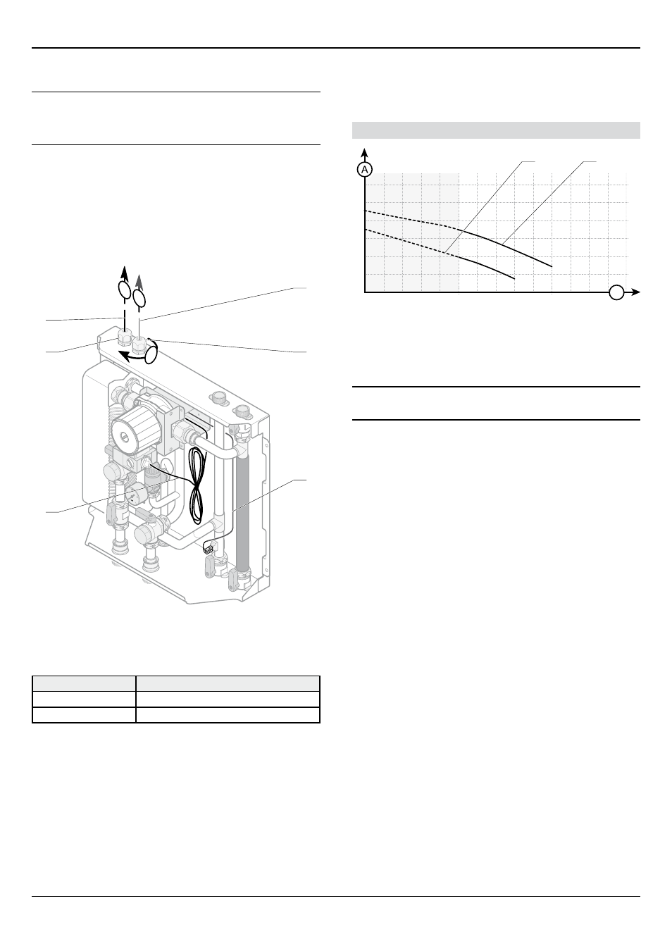
Pump flow / pressure curve
60
50
40
30
20
10
0
300
600
900
1200
B
2
1
Key
1 Speed 2
2 Speed 3 (factory setting)
A Available pressure (kPa)
b flow in the circuit (l / h)
i
Speed 1 is not applicable to this system.
10 Specific adjustment
• Refer to the system’s installation manual to adjust the
installation.