Installation – Glow-worm Clearly Hybrid - Compact Hydraulic Module HB User Manual
Page 10
0020096881_02 - 08/10 - Glow-worm
- 8 -
INSTALLATION
7 Hydraulic connection
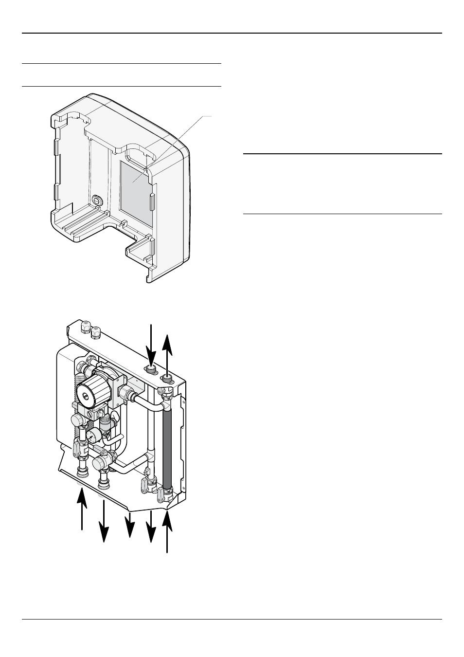
i
A label located inside the cover enables the
identification of the module’s hydraulic connections.
1
Key
1 Hydraulic connection label
B
A
C
D
E
F
G
Key
A Boiler flow circuit Ø ¾"
B Boiler return circuit Ø ¾"
C Heating return circuit Ø ¾"
D Heating flow circuit Ø ¾"
E Safety valve discharge
F Heat pump return circuit Ø 1"
G Heat pump flow circuit Ø 1"
• Take care to clean the pipes before assembly removing any
debris or burrs. Grease and oils may need to be removed
they are not possible to remove by cleansing and flushing.
Foreign bodies in the system may enter the appliance and
interrupt its operation.
• Do not use any solvent products, due to the risk of damaging
the circuit.
a
Do not perform any 'hot work' directly under
the appliance, this may cause damage to the
appliance base. Heat may also damage the
isolation valves.
Always pre-assemble pipes before fitting them to
the appliance.
• Only use original seals supplied with the appliance.
• Check that there are no leaks.