Mounting and installation – Glow-worm Clearly Heat Pumps Envirosorb3 User Manual
Page 14
0020154078_00 - 02/13 - Glow-worm
14
MOUNTING AND INSTALLATION
4.4
Electrical
Installation
e
Danger!
Risk of electric shock due to an improper electri-
cal connection!
Improper electrical connection can cause electric
shock or might negatively affect the operational
safety of the product and might cause material
damage.
•
The electrical connection of the product must
be carried out only by a suitably qualified per-
son.
20 mm max.
2
1
Key
1 Electrical
wires
2 Insulation
When you connect the electrical wires to a connector on the
electronic board:
∙ Keep a distance of a maximum of 20 mm between
connector and the start of the insulation.
∙ Fix the electrical cables with the clamps installed inside
the heat pump.
4.4.1
Connecting the power input (mains
connection)
The external wiring must be earthed, with correct polarity and
in accordance with current standards.
∙ Always check that the Live and Neutral are connected
correctly.
The cables connecting the switchboard and the heat pump
must be:
- Suitable for a fi xed installation.
- weather resistant.
- equipped with wires adapted to appliance’s power rating.
∙ Connect the heat pump to an electrical panel via an
independent protection system (diff erential breaker with at
least 3 mm between each contact).
Additional protection may be required during installation to
ensure surge category II.
The power supply cut-off devices must allow complete
disconnection of the power under the conditions required for
over-voltage category III.
4.4.1.1 230V heat pump
b
Caution!
Risk of damage from too great voltage.
At mains voltages higher than 253 V, electronic
components may be destroyed.
•
Make sure that the rated voltage of the mains
is 230 V.
b
Caution!
Risk of malfunction due to the electrical supply.
If the imbalance between the phases of the elec-
trical supply is too large, a malfunction may occur.
•
Install the appliance on a electrical supply with
a maximum imbalance of 2% between phases.
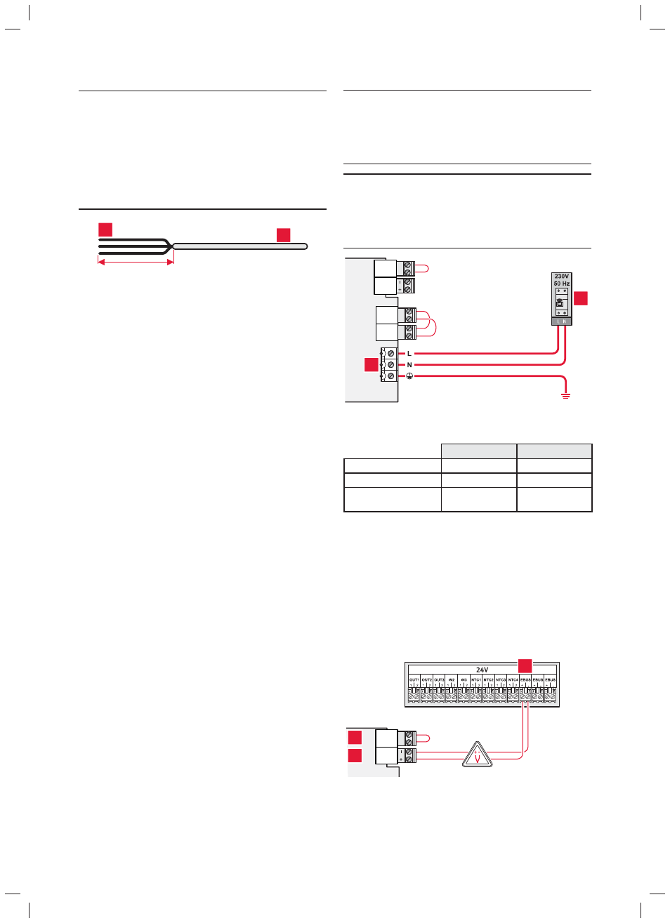
X4
X9
EBUS
X7 FLOOR H
X2
21
1
2
Key
1 Heat pump power supply connection
2 Installation power supply and electric protection
Envirosorb3 8
Envirosorb3 11
Electricity supply
1/N/PE 230V 50Hz 1/N/PE 230V 50Hz
Circuit breaker
16 A - Type C or D
20 A - Type C or D
Recommended cable size
230V
3G x 2.5 mm²
3G x 2.5 mm²
∙ Connect a cable to the appliance’s power terminal.
∙ Pass the cables through the heat pump cable gland (see
section 4.4.3).
∙ Suitable breaker size and type must be used to fi t
installation site requirements.
∙ Cable size must be suitable for installation site
requirements
4.4.2
24V cable connection
X4
X9
EBUS
X7 FLOOR H
1
2
3
Key
1 eBUS connection to the heat pump (comply with the polarity ±)
2 Connect
the
fl oor heating protection device to the heat pump
3 e-BUS connection terminal on the control box