Mounting and installation – Glow-worm Clearly Heat Pumps Envirosorb3 User Manual
Page 12
0020154078_00 - 02/13 - Glow-worm
12
MOUNTING AND INSTALLATION
4.2
Mounting the appliance
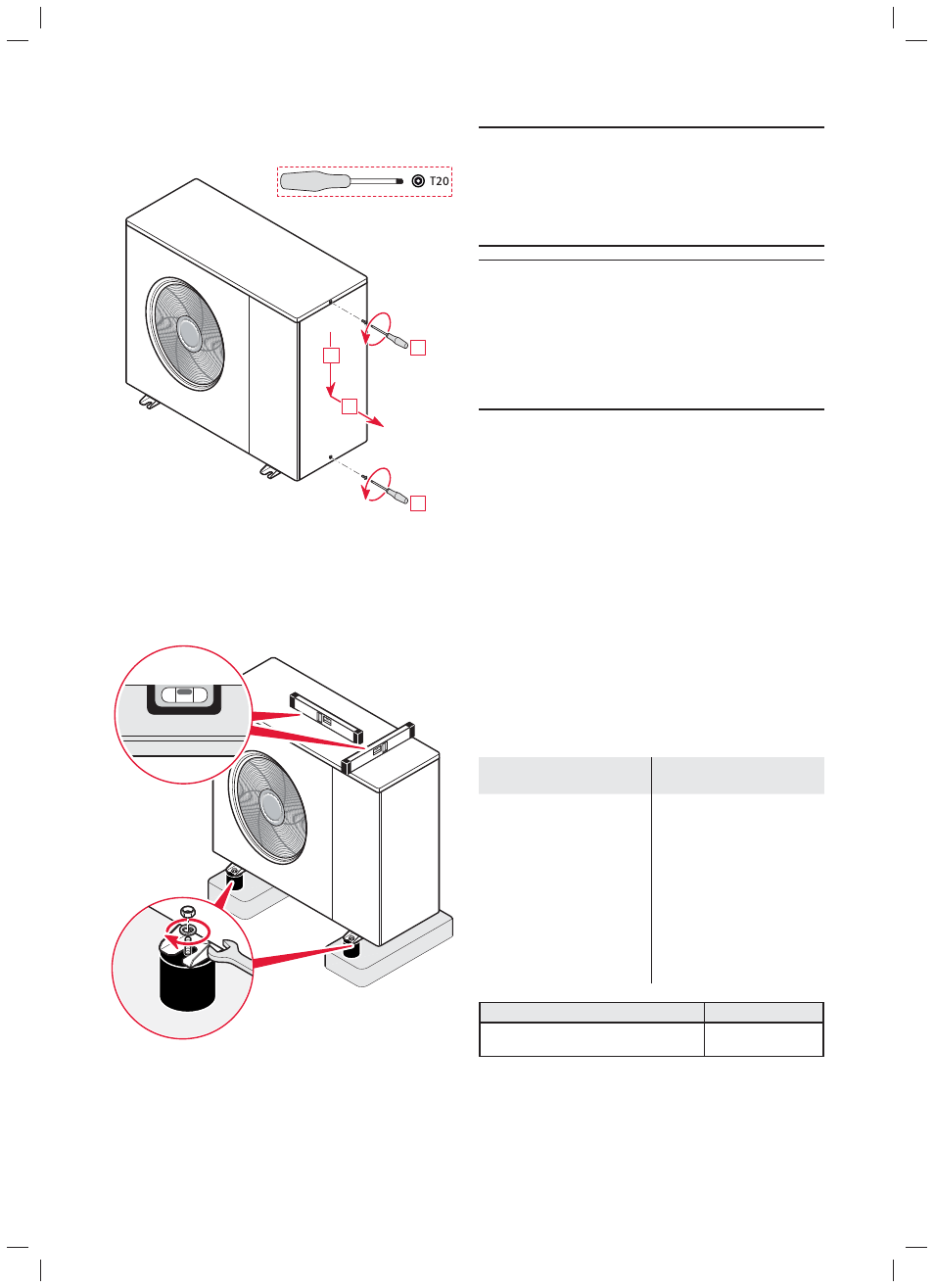
4.2.1
Opening the appliance
B
A
A
C
4.2.2
Positioning the appliance
i
The heat pump must be installed with the anti-
vibration pads supplied. The anti-vibration pads
are used to raise the unit, limit the transmission
of vibrations and to facilitate the discharge of
condensates.
∙ Install the appliance level so that the condensates drain
correctly.
4.3 Hydraulic
installation
b
Caution!
Risk of damage caused by contaminated lines!
Foreign bodies such as welding remnants, sealing
residue or dirt in the supply lines can cause dam-
age to the product.
•
Flush the supply lines thoroughly before instal-
lation.
b
Caution!
Risk of damage due to corrosion.
If plastic pipes that pass oxygen are used in the
heating installation, this may corrode or sludge
up the appliance’s heating circuit or the appliance
itself.
•
If you use plastic pipes that pass oxygen in the
heating installation, add a corrosion inhibitor
to the circuit water.
4.3.1 Hydraulic
connection
i
Insulate the pipes (between the heat pump and
the installation including those underground)
with an UV- and high-temperature-resistant insu-
lation.
i
In order to avoid the transmission of vibrations to
surrounding structures, flexible hoses of at least
750mm in length should be used for the hydraulic
connections from the heatpump.
∙ Do not weld pipes mounted up : this operation may
damage the seals.
∙ If the heat pump is not located at the highest point of the
hydraulic circuit, install additional bleed valves in suitable
places.
∙ Install the following components on the heat pump return
circuit.
Installation with
hydraulic module
Installation without
hydraulic module
- a drain tap
- an air separator (if
necessary)
- an anti-sludge fi lter
- an expansion tank, if the
length of the hydraulic circuit
is greater than the max.
permitted length (see table
below)
- a 3 bar (3 x 10
5
Pa) safety
valve if the hydraulic module
does not have one
- a drain tap
- an air separator (if
necessary)
- an anti-sludge fi lter
- an expansion tank suitable
for the complete hydraulic
installation
- a 3 bar (3 x 10
5
Pa) safety
valve
- a pressure gauge
(recommended)
Max. length of the hydraulic circuit
DN 28
In the case of the installation of a module
without an expansion tank
30 m