High performance ice fishing gear, Assembly instructions – Eskimo 69164 User Manual
Page 4
Eskape
™
400 Hardwater Series (69164)
Page 4
GetEskimo.com
HIGH PERFORMANCE ICE FISHING GEAR
1-800-345-6007
®
ASSEmBly INSTRuCTIONS
Tools Needed: (2) 7/16” wrenches & (1) 3/8” wrench.
ASSEMBLY NOTE: This ice shelter should be assembled in
a garage or basement setting due to the time and length of
assembly. Identify and familiarize yourself with all parts and
hardware before assembly. Allow 1-3 hours for assembly.
ASSEMBLY NOTE: The use of a cordless drill with socket will
make assembly of your ice shelter much quicker. Be sure to
set the drill speed low so you do not over tighten any nut and
bolt combinations.
ASSEMBLY NOTE: If a High-Speed Tracking Kit will be pur-
chased for use on this ice shelter, it should be mounted to the
sled before assembly of the ice shelter for convenience.
ImPORTANT ASSEmBly TIP: DO NOT fully TIGHTEN ANy
NuT AND BOlT COmBINATIONS uNTIl All BOlT-ON PARTS
ARE ASSEmBlED TOGHETHER! fINGER TIGHTEN ONly!
THIS WIll HElP HOlE AlIGNmENT Of All PARTS.
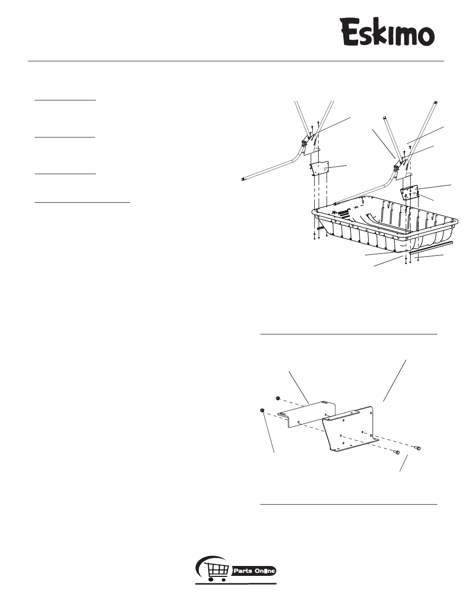
1. Attach (1) left hinge riser (68052) and (1) sled support strap (68161) to
the upper left side of sled lip using (3) provided 1/4-20 x 1” hex head
bolts, nyloc nuts and (1) washer.
SEE fIGuRE 1.
2. Repeat step 1 to attach (1) right hinge riser (68053) and (1) sled sup-
port strap to the upper right side of sled lip.
SEE fIGuRE 1.
3. Attach (1) left hinge assembly (68146) to the top of left hinge riser
and (1) right hinge assembly (68145) to the top of right hinge riser
using (4) provided 1/4-20 x 3/4” hex head bolts and nyloc nuts.
SEE
fIGuRE 1.
NOTE: Be sure hinge assemblies are orientated as shown in
FIGURE 1, with high sides of hinges placed to the front of sled.
Snap buttons on hinge poles should face inward, towards each
other.
4. Repeat steps 1-3 for attaching remaining left and right hinge risers and
hinge assemblies to the opposite side of sled to create the double sided
configuration.
fIGuRE 1 image will apply to other side also.
NOTE: STEPS 5-14 FOR SEAT KIT ASSEMBLY SHOULd BE dONE
FOR BOTH SEAT KITS, ONE FOR EACH SIdE OF SLEd.
5. Attach (2) seat kit mount brackets (68304) to each hinge assembly
using (4) provided 1/4-20 x 3/4” hex head bolts and nyloc nuts
SEE
fIGuRE .
6. Slide the pre-assembled rod holder assembly (68449) into the T-slot
of either bench seat rail. Doing so makes this bench seat rail the front
rail and will be positioned beneath your legs during use.
7. Attach (2) bench seat rails (68301) to the top side of seat kit mount
brackets using (4) provided 1/4-20 x 2-1/2” bolts, nyloc nuts and (4)
washers.
SEE fIGuRE 3A. Make sure the rail with the rod holder
assembly is in front, so it will be positioned beneath your legs during
use.
fIGuRE 1
left hinge
riser
(2) 1/4” x 3/4” bolts
fIGuRE (left side shown)
(2) 1/4” nuts
seat mount bracket
hinge riser
left hinge
assembly
(2) 1/4” x
3/4” bolts
sled support strap
high side
of hinge
(6) 1/4” x
1” bolts
(6) 1/4” nuts
(2) 1/4” washers
front bolt only
right hinge
assembly
right hinge
riser