Assembly instructions, Eskimo, Flipmo – Eskimo 15450 User Manual
Page 4: 2 inferno
Check for parts online at
www.GetEskimo.com or call 800-345-6007 M-F 8-5 CDT
4
Operator's Manual
ESKIMO
®
FlipMo
™
2 Inferno
ASSEMBLY INSTRUCTIONS
Tools needed – (2) 7/16” wrenches, a Phillips head screwdriver,
rubber mallet (optional), and a cordless drill (optional).
Assembly Note: This ice shelter should be assembled in
a garage or basement setting due to the time and length
of assembly. Identify and familiarize yourself with all
parts and hardware before assembly. Allow 1-3 hours for
assembly.
Assembly Note: The use of a cordless drill with socket will
make assembly of your ice shelter much quicker. Be sure to
set the drill speed on low so you do not over tighten any nut
and bolt combination.
Assembly Note: If a tracking kit is purchased with the
shelter it should be mounted to the sled before assembly
of the ice shelter for convenience.
Important Assembly Tip: Do NOT fully tighten any nut and
bolt combination until instructed in later notes. This will
help hole alignment of all parts.
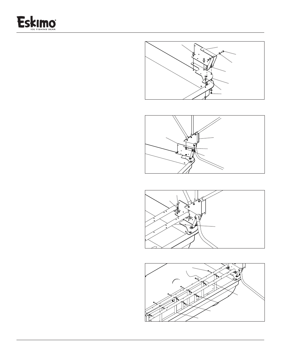
1. Attach the Hinge Riser A (68052) and corner mount plate
(11599) to the tub using (4) ¼-20 X 1” bolts, (8) ¼” washers
and (4) ¼-20 nylock nuts. Align the hole pattern on the
plate corner mount (11599) with the left hinge assembly
(69307L) to the matching hole pattern on the sled. Insert
bolts starting with hole #1 (using a ¼-20 x 1” bolt) then move
on to #2, #3 and #4, tightening bolt/nut combinations as
you go. SEE FIGURE 1
Note: Hole 3 and 4 will be used to attach the versa seating
system. Do not fully tighten these bolts as they will need to
be taken off again for a later step.
2. Repeat step 1 on the opposite side using Hinge Riser B
assembly (68053). SEE FIGURE 1
3. Attach the (2) hinge support braces (11203) to both the
Hinge Riser A (68052) and Hinge Riser B (68053) using
(4) ¼-20 x ¾” bolts, (4) ¼” washers, and (2) ¼-20 nylock
nuts. First attach the hinge support brace (11203) to hole
#5 on the corner mount plate (11599). SEE FIGURE 1
Note: If the hole alignment is off or looks too far apart,
rotate the hinge support brace and try again. This part will
only bolt on one way.
4. Attach the Hinge Assembly A (68141) to Hinge Riser A (68052)
using (2) ¼-20 X ¾” bolts, (4) ¼-20 nylock nuts and ¼” washers.
SEE FIGURE 2
5. Repeat step 3 on the opposite side using the Hinge Assembly
B (68142). SEE FIGURE 2
Note: Be sure the hinge assembly is on correctly with the
high side of the hinge placed towards the front of the sled.
FIGURE 1
Hinger Riser A
corner mount plate
¼-20 X ¾” bolt
¼” washers
¼-20 nylock nut
#4
#2
#1
#3
(not shown)
F
FIGURE 2
hinge support brace
Hinge Riser A
Hinge Assembly A
¼” washer
¼-20 nylock nut
#5
FIGURE 3
seat rail
¼-20 X 1” bolt
¼” washer
#3
#4
FIGURE 4
seat rail
¼-20 X 2¼” bolt
¼” washer
¼-20 nylock nut
¼-20 X 1” bolts
¼-20 X ¾” bolt
vertical frame support
Note:
(2) ¼-20 x ¾” bolts
not shown