ENMET SE-5175 User Manual
Page 7
SE-5175
ENMET Corporation
5
3.2 Wiring the SE-5175
The electrical installation should conform to appropriate electrical codes, such as the National Electrical Code in the United
States.
W
ARNING
:
The compliance of the installation to appropriate codes is not
ENMET
’s responsibility.
C
AUTION
:
Area must be declassified during installation.
Run conduit and 16
AWG
(1.5
MM
2
)
wires to the enclosure from the power supply and controller. Or use a 3 wire power cord of
0.20 to 0.35” in diameter.
After releasing the screws and lifting the cover and exposing the terminal strips on the bottom of the circuit board.
Connect the wires from the controller (power supply) to the supplied J4 plug then attach to J4 terminal.
3.2.1 Power Supply
Upon supplying power to the
SE-5175
:
The green power on LED is lit.
The display backlight is lit, and instrument will step through a start-up sequence: unit serial number and software revision
may be shown on the display.
The instrument may go into alarm briefly, but the sensors stabilize quickly. If the instrument persists in alarm, acknowledge the
alarm by pressing the
S
ELECT
button. If alarm persists longer than 30 minutes, call
ENMET
customer service personnel.
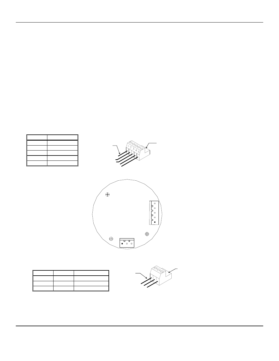
J4
P
LUG
–
T
ERMINAL TO
C
ONTROLLER
W
IRING
Position
Function
1 +
24
V
DC
power
2
GND
3
4 - 20 mA out
4*
RS-485 D+
5*
RS-485 D–
*Contact
ENMET
for Modbus Address information
J8
P
LUG
–
T
ERMINAL TO
S
ENSOR
W
IRING
Position Function
Sensor
1
V +
Red
2
Signal
White
3
GND
Black
Figure 4: Power Terminal Connections SE-5175
Plug J4
To J4
Wires to
Controller
5
4
3
2
1
J4
J8
1 2 3
Circuit Board Bottom View
Plug J8
To J8
Wires to
Sensor
2
3
1