Table 3: wiring at isb, Figure d: wiring to isb in c – ENMET SDS-97D User Manual
Page 7
SDS – 97D Sensor / Transmitter
ENMET Corporation
5
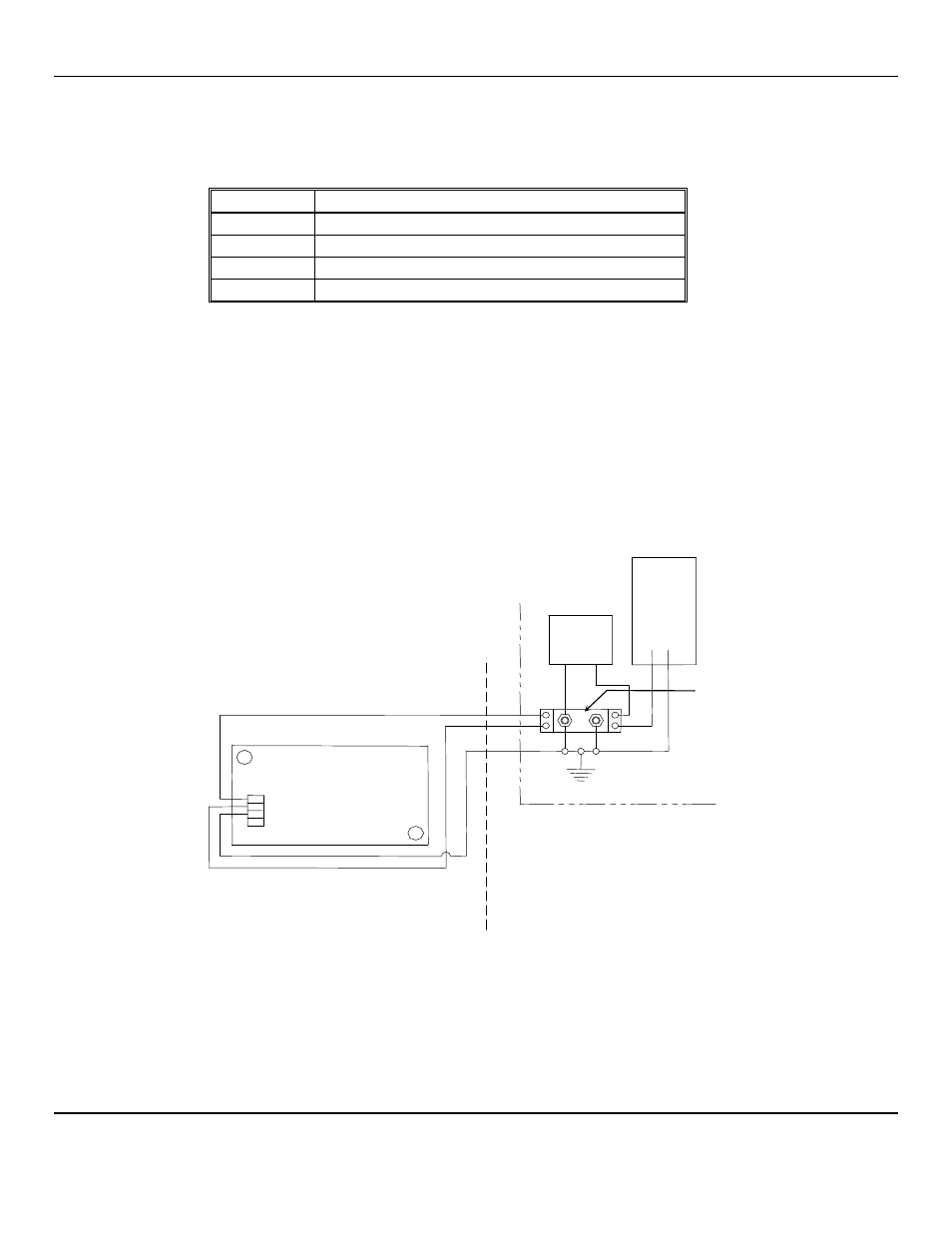
If the sensor/transmitter enclosure is grounded, connect the shield at the control.
The terminals on the barrier are clearly numbered, and a schematic of the barrier is on a label on the barrier housing. At the
barrier, the connections are as shown in Table 3 and Figure D:
Table 3: Wiring at ISB
Position
Function
1
V+, power supply, safe side
2
signal, the positive side of the loop, safe side
3
V+, power supply, hazardous side
4
signal, the positive side of the loop, hazardous side
The negative side of the loop (from J3-3 at the sensor/transmitter), the negative side of the readout device, and the negative side
of the 24
V
DC
power supply are all connected to earth ground at the barrier. When working in a hazardous area, even if it has
been temporarily declassified, it is good practice to connect the negative side of the loop to earth ground first, and, if
disconnecting a sensor/transmitter, disconnect the same wire last. The two ground points on the barrier must be securely
connected to earth ground with a connection that cannot be interrupted by separating a connector or pulling the plug of a line
cord.
A regulated 24
V
DC
power supply must be used to provide the V+ power to the sensor/transmitter. Supplying over 26
V
DC
blows the fuses in the barrier, and the barrier must be replaced.
The maximum resistance of the power supply wire is 125 ohms when 24
V
DC
is supplied through the barrier. The maximum
combined resistance of the positive loop wire and the readout device is 340 ohms. Very little current flows in the negative loop
wire.
Figure D: Wiring to ISB in C
ONTROL
When the sensor/transmitter is mounted and wired, assure that the cover gasket is in place, replace the cover, and secure it with
the two cover screws.
Allow the sensor/transmitter to stabilize for 3 to 24 hours.
C
ONTROL
See control manual
J3
1 V+
2 Signal
3 Ground
4 Shield, if necessary
S
ig
n
a
l
G
ro
u
n
d
ISB, MTL 787S+
SDS – 97D
Sensor / Transmitter
–
+
3
4
1
2
24 V
DC
Regulated
Power
Supply
Earth ground
Hazardous Area
Safe Area