Table 2: wiring at s/t, Figure c: wiring to isb – ENMET SDS-97D User Manual
Page 6
SDS – 97D Sensor / Transmitter
ENMET Corporation
4
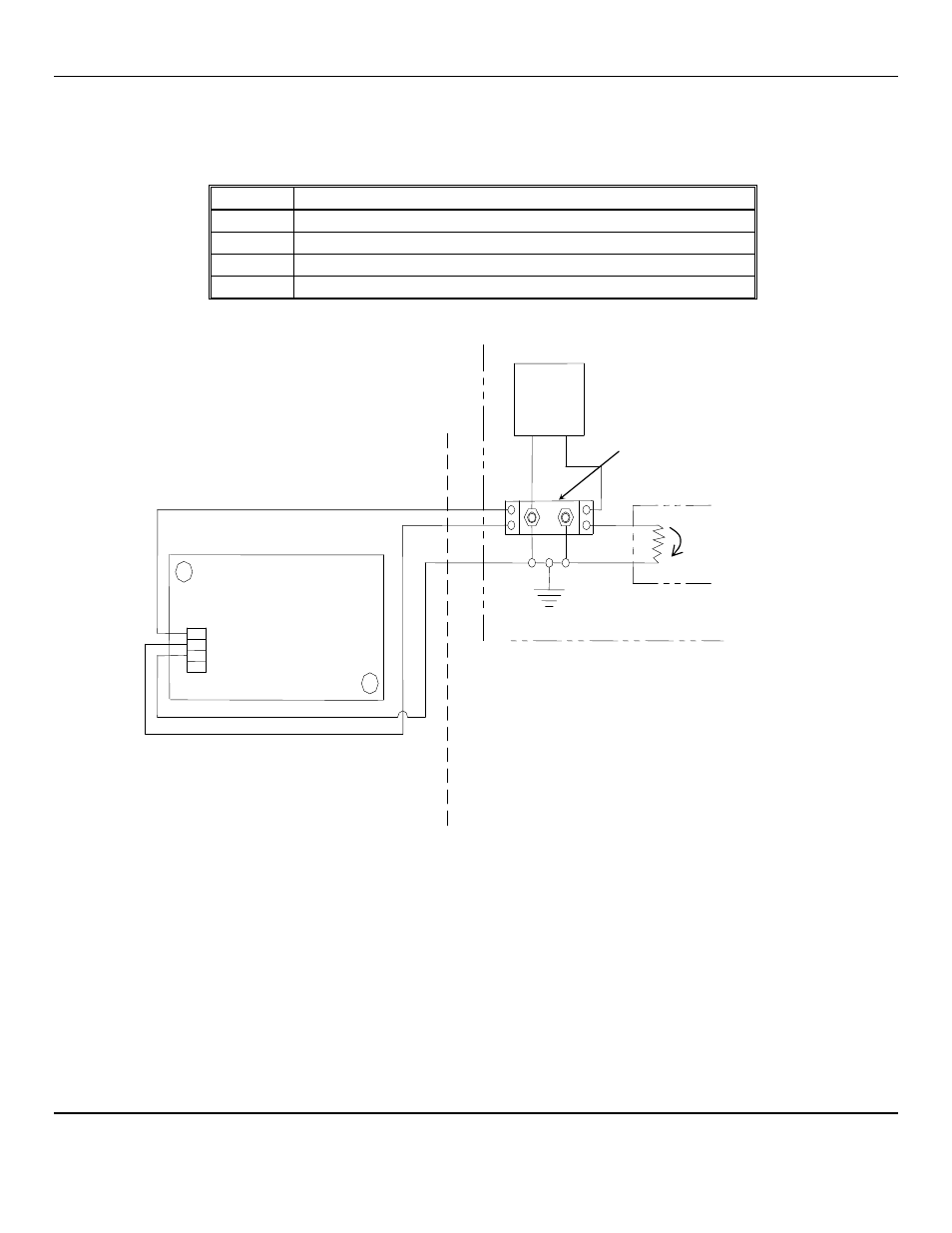
2.2.2 Sensor/Transmitter with ISB
Installation with a recommended Intrinsic Safety Barrier properly connected and grounded renders the sensor/transmitter
nonincendive as defined by the National Electrical Code. An MTL 787S+ barrier is recommended connected as shown in
Figure C. Connections at the sensor/transmitter are shown in Table 2 as follows:
Table 2: Wiring at S/T
Position
Function
J3-1
V+, the power supply
J3-2
signal, the positive side of the loop
J3-3
ground, the negative side of the loop
J3-4
shield, only if the sensor/transmitter enclosure is not grounded
Figure C: Wiring to ISB
When the sensor/transmitter is mounted and wired, assure that the cover gasket is in place, replace the cover, and secure it with
the two cover screws.
Allow the sensor/transmitter to stabilize for 3 to 24 hours.
1 V+
2 Signal
3 Ground
4 Shield, if necessary
SDS – 97D
Sensor / Transmitter
3
4
24 V
DC
Regulated
Power
Supply
Readout
4-20mA
Earth ground
J3
Safe Area
Hazardous Area
1
2
ISB, MTL 787S+
–
+