2 installation, Table 1: wiring without isb, Figure b: direct wiring to c – ENMET SDS-97D User Manual
Page 5
SDS – 97D Sensor / Transmitter
ENMET Corporation
3
2.2 Installation
• The interior of a sensor/transmitter with the cover removed is shown in the accompanying Figure A, for reference during
these operations.
• Remove the cover of the sensor/transmitter by removing the two black cover screws.
• Mount the sensor/transmitter to an appropriate stable vertical surface with the sensor facing downward.
C
AUTION
:
Since the sensor/transmitter detects gas only at the sensor location, pay attention to the possible sources of gas,
the density of the gas, locations where the gas may be confined and locations where the gas may damage or injure property or
personnel, when choosing locations of sensor/transmitters.
• Mount the sensor/transmitter using the two mounting holes in the corners of the enclosure. For maximum RFI protection
the enclosure should be grounded to earth ground, either by means of the mounting screws, a conductive conduit, or a wire
connected to earth ground.
• The interface terminal strip J3 is located at the left edge of the internal circuit board. Wires enter through the port in the left
wall of the enclosure, that is supplied with a watertight strain relief. Wiring may be with good quality three conductor
shielded cable or with three insulated wires in metallic conduit. When the watertight strain relief is removed, the hole at the
entry point is threaded 3/8 NPT female; use appropriate watertight conduit fittings.
2.2.1 Sensor/Transmitter without ISB
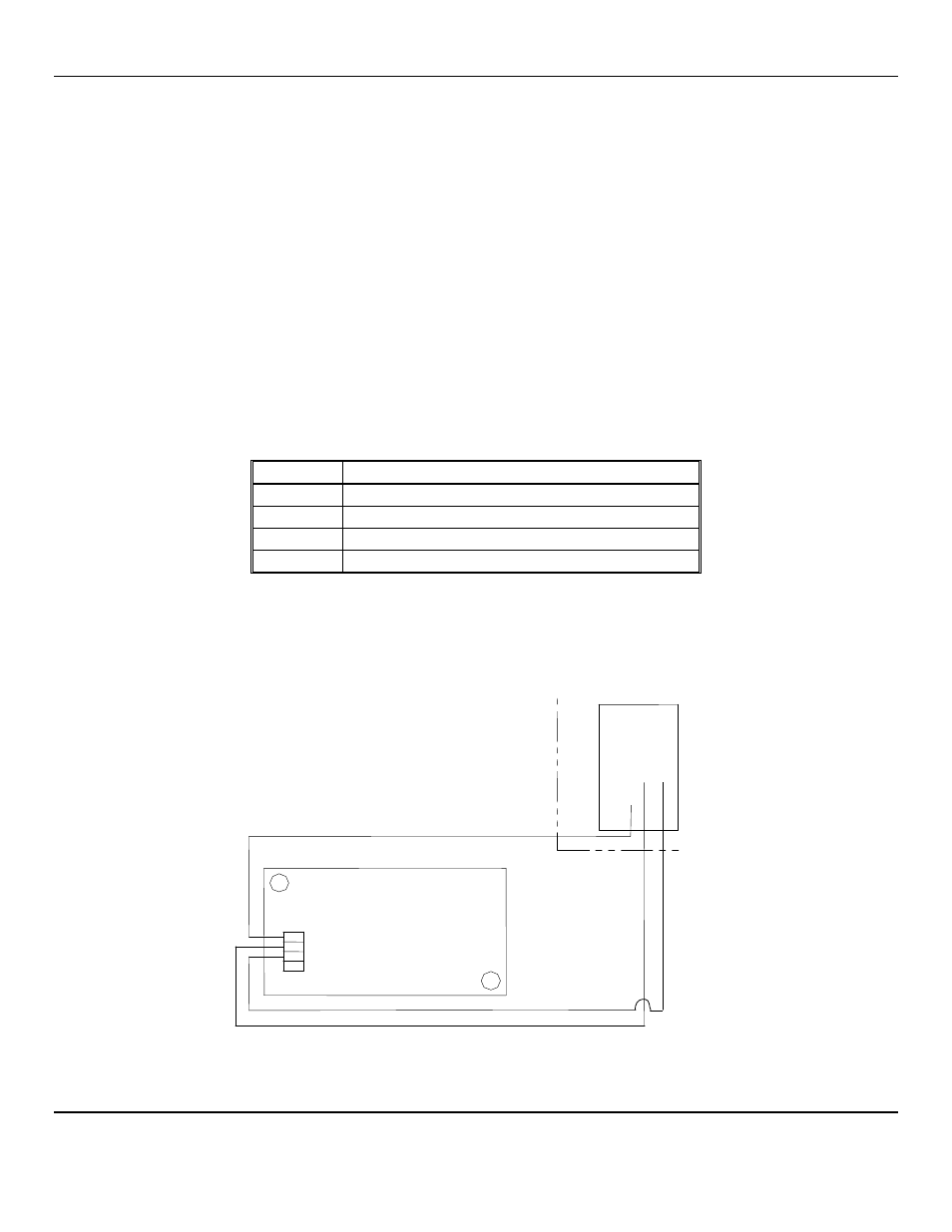
Wiring without Intrinsic Safety Barriers to the following points shown in Table 1 and Figure B:
Table 1: Wiring Without ISB
Position
Function
J3-1
V+, the power supply
J3-2
signal, the positive side of the loop
J3-3
ground, the negative side of the loop
J3-4
shield, earth ground
Maximum resistance of the power supply wire is 300 ohms when 24
V
DC
is supplied at the control, and the maximum load
resistance of the signal loop is 300 ohms. A very small current flows in the negative signal wire. To avoid current loops in the
earth ground circuit, connect one end, only, of the shield or conduit to earth ground.
Connect the other ends of the three wires to the appropriate terminals of the control or computer used to monitor the 4-20 mA
sensor/transmitter signal, and the power supply. A power supply must be capable of providing 10 to 24
V
DC
at the
sensor/transmitter. Maximum current draw is 45 mA.
Allow the sensor/transmitter to stabilize for 3 to 24 hours.
Figure B: Direct Wiring to C
ONTROL
1 – V+
2 – Signal
3 – Ground
4 – Shield
J3
V
+
S
ig
n
a
l
G
ro
u
n
d
C
ONTROL
See control
manual
SDS – 97D
Sensor / Transmitter