ENMET EX-5150-MOS User Manual
Page 7
EX-5150-MOS
ENMET Corporation
5
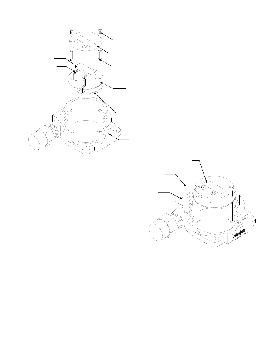
Figure 3: Terminal Positions EX-5150-MOS Sensor/Transmitter
When wiring is complete re-assemble the
EX-5150-MOS
. Use caution when installing the overlay so as not to damage the
magnetic switches. Put the cover back on the S/T Do Not apply power to the S/T without the cover in place.
Sensor/Transmitter
Enclosure Cutaway View
Printed Circuit Board
(PCB)
Display Overlay
Display Overlay Screws
(2 places)
Display Overlay Standoffs
(2 places)
Magnetic
Switches
(2 places)
Magnetic Switches
(2 places)
Printed Circuit Board (PCB)
J4 and J8 Terminals are located on the
bottom side of PCB
Display Overlay
Display
Optional
Relay Output Circuit Board
See also other documents in the category ENMET Measuring instruments:
- Formaldemeter htV (14 pages)
- PPM Formaldemeter™ htV-m (19 pages)
- PGD2 (34 pages)
- PGD2Manual.pdf (28 pages)
- RECON/4 (10 pages)
- RECON-4 (17 pages)
- RECON-IS (15 pages)
- RECON/B SERIES (17 pages)
- RECON Series (16 pages)
- OMNI-4000 (72 pages)
- QUADRANT (26 pages)
- SMARTLOGGER (19 pages)
- SPECTRUM (32 pages)
- SPECTRUM CO-RAL (18 pages)
- SPECTRUM ON-LINE (30 pages)
- SPECTRUM-RAL (15 pages)
- SPECTRUM-RAL-DC (17 pages)
- SPECTRUM SP (20 pages)
- TARGET (36 pages)
- TDX Series (8 pages)
- TX-2000 (24 pages)
- AM-5150 (23 pages)
- AM-5175 (21 pages)
- ENG – 97D STAND-ALONE (12 pages)
- GSM-60 (39 pages)
- ISA-60M with MRI-5175 (28 pages)
- MRI-5175 (2 pages)
- MEDAIR 2200 (40 pages)
- PROAIR 2200 (40 pages)
- CP-60 (23 pages)
- EX-5100 (18 pages)
- EX-5175-EC (16 pages)
- ISA-200-RAL (O) (24 pages)
- ISA-40 (19 pages)
- ISA-40M (18 pages)
- ISA-44-2OD (32 pages)
- ISA-44-RALE-OD (38 pages)
- ISA-44-RAL-OD (28 pages)
- ISA-M (15 pages)
- ISA-RAL-M (22 pages)
- MedAir 2000 (30 pages)
- CD-1300-ST (13 pages)
- EX-5120 (18 pages)
- EX-5130 (16 pages)