ENMET EX-5150-MOS User Manual
Page 6
EX-5150-MOS
ENMET Corporation
4
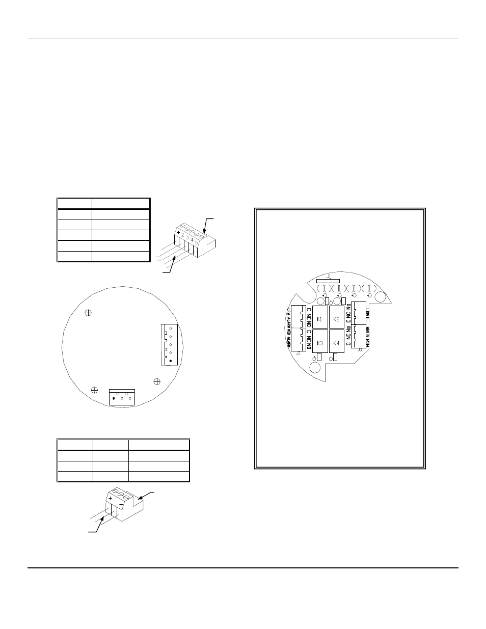
3.2 Wiring the EX-5150-MOS to a Control Unit
C
AUTION
:
Area must be declassified during installation.
Run conduit and 16
AWG
(1.5
MM
2
)
wires to the enclosure from the power supply and controller. If the
EX-5150-MOS
is
installed in a hazardous location as defined by the National Electrical Code, then ALL wiring must be in accordance with the
National code and any local governing codes.
Open the enclosure, and remove the 2 screws that retain the display overlay to the circuit board.
Use caution when removing the over lay. Do not damage the magnetic switches.
Remove the two overlay standoffs and remove the circuit board, exposing the terminal strips on the bottom of the circuit board.
Do not disconnect the circuit board wiring.
Connect the wires from the controller (power supply) to the supplied J4 plug then attach to J4 terminal.
Connect the wires from the sensor to the supplied J8 plug then attach to the J8 terminal.
See Figure 3 for locations
J4
P
LUG
–
T
ERMINAL TO
C
ONTROLLER
W
IRING
Position
Function
1 +
24
V
DC
power
2
GND
3
4 - 20 mA out
4*
RS-485 D+
5*
RS-485 D–
*Contact
ENMET
for Modbus
Address information
J8
P
LUG
–
T
ERMINAL TO
S
ENSOR
W
IRING
Position Function
MOS Sensor
1 +
Heater
Orange
2
Signal
Blue
3 –
GND
Brown
Relay Output Board Bottom View
Optional Relay Output Board
It is recommended that the auxiliary
alarm be powered separately.
Use 14 – 20
AWG
(2.5
–
0.5
MM
2
) wire.
When on power the relays are energized.
Relays are rated at 0.5 Amp continuous.
N
OTE
: Auxiliary alarms should be powered from
an independent power source separate form
the instrument power to avoid alarm failure
due to controller malfunction.
ALL wiring must be in accordance with the
National code and any local governing
codes.
Circuit Board Bottom View
5
4
3
2
1
J 4
J 8
1 2 3
P l u g J 4
To J4
Wires to
Controller
P l u g J 8
To J8
Wires to
Sensor
2