0 installation of the cp-10 – ENMET CP-10 User Manual
Page 6
CP-10
ENMET Corporation
4
3.0 Installation of the CP-10
The
CP-10
is supplied with a strain relief for a power line cord. Use this fitting or connect a conduit fitting when supplying
power to the unit.
N
OTE
:
This control panel is N
OT
rated for hazardous locations. The control panel must be located in a NON-Hazardous area.
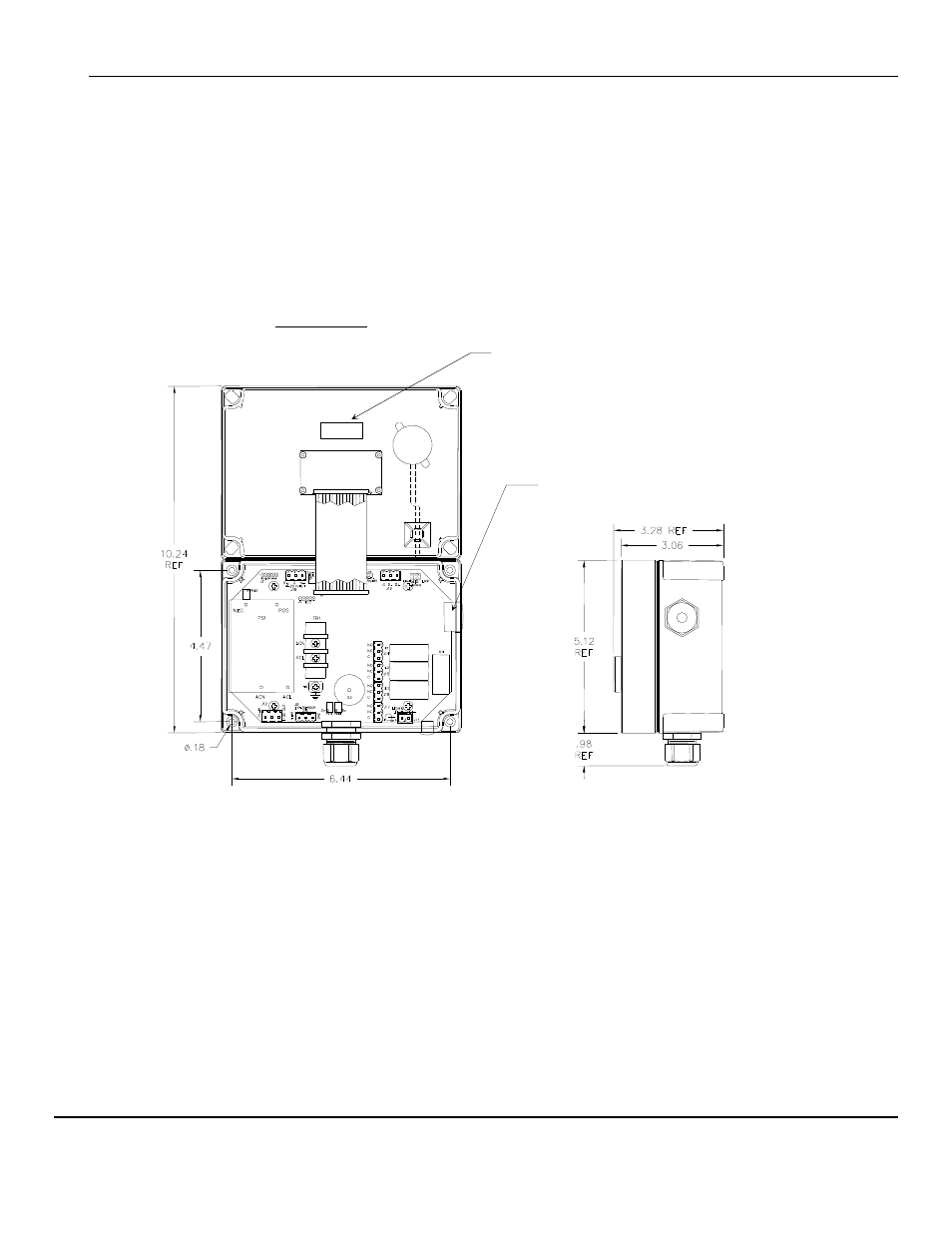
3.1 Mounting CP-10
Mount the
CP-10
instrument on an appropriate vertical surface, leaving room for lid to be opened, using the mounting holes
provided. Avoid areas with excessive vibration or temperature extremes. The holes in the bottom of the enclosure are 0.18
inch in diameter and form a 6.44
″ x 4.47″ rectangle. See Figure 3
It is recommended to use #8 drywall anchors and screws for mounting the
CP-10
to a drywall/sheetrock surface.
Dimensions are in inches.
F
IGURE
3: Mounting CP-10
Right Side View
Cover Inside View
Opened Upward
Attached to Base
Sensor Heater Voltage Label
Access for Sensor / Remote Sensor Wiring