ENMET CP-10 User Manual
Page 11
CP-10
ENMET Corporation
9
4.2 Normal Display Mode
When the
CP-10
is installed as described in section 3, the
POWER
green LED is on, the display is lit and the measurement
designator: ppm, LEL or % is displayed by the
CP-10.
The red alarm and fault LEDs are not lit.
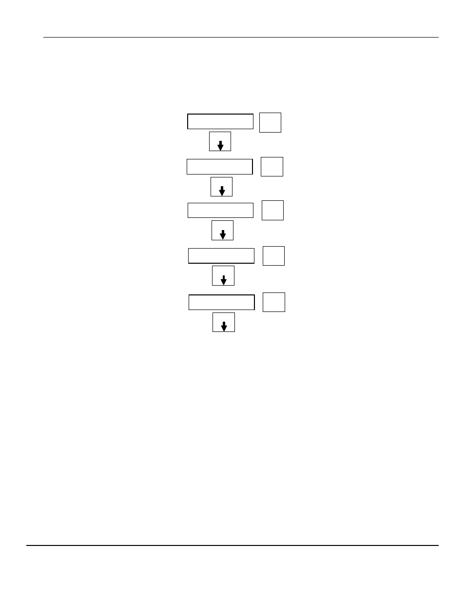
To advance through displays of operational information press the
M
ENU
button.
N
OTE
:
Software revision may cause variations of display output.
See sequence of operational information below:
Example:
Display Measurement of the target gas
Press
M
ENU
button
Display indicates Alarm 1 Set point
Press
M
ENU
button
Display indicates Alarm 2 Set point
Press
M
ENU
button
Display indicates Alarm 3 Set point
Press
M
ENU
button
Display indicates mA Span range
(Full Scale)
Press
M
ENU
button
Display returns to gas measurent
Operational Display Flow Chart
4.2.1 Alarm Conditions
CP-10
There are three alarm set points available. These alarm points are normally set at established safety levels, such as the OSHA
Permissible Exposure Limit (PEL) for toxic gases or recognized standards below the Lower Explosive Limit for combustible
gases.
These alarm set points can be changed within limits; see the maintenance section of this manual for the procedure.
When the Oxygen, Toxic or combustible gas concentration reaches the alarm set point, the associated red LED is lit, the
associated relay changes state, and the audio alarm is activated.
Pressing the
S
ELECT
button can temporally disable the Audio Alarm. The horn will be disabled for about five minutes. If a
second alarm condition occurs during this time the horn will re-activate. If the alarm condition(s) have ended during this time
the horn will not re-activate.
0ppm
A1:
05
Select
➨
Select
➨
Menu
Menu
A2:
10
Select
➨
Menu
A3:
20
Select
➨
Menu
mA:
50
Select
➨
Menu