ENMET AM-5175 User Manual
Page 6
AM-5175
ENMET Corporation
4
3.0 Installation of the
AM-5175
The
AM-5175
is supplied with a strain relief and a standard U.S. 3 prong power line cord.
N
OTE
:
This control panel is N
OT
rated for hazardous locations. The control panel must be located in a NON-Hazardous area.
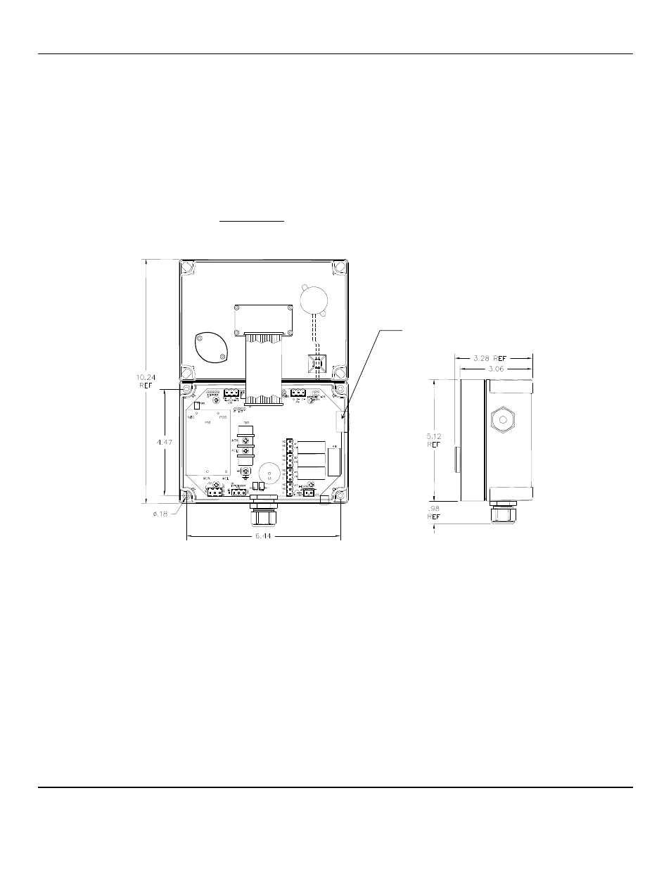
3.1 Mounting AM-5175
Mount the
AM-5175
instrument on an appropriate vertical surface, leaving room for lid to be opened, using the mounting holes
provided. Avoid areas with excessive vibration or temperature extremes. The holes in the bottom of the enclosure are 0.18
inch in diameter and form a 6.44
″ x 4.47″ rectangle. See Figure 3
It is recommended to use #8 drywall anchors and screws for mounting the
AM-5175
to a drywall/sheetrock surface.
Dimensions are in inches.
Figure 3: Mounting AM-5175
Right Side View
Cover Inside View
Opened Upward
Attached to Base
Access for Sensor / Remote Sensor Wiring
- Formaldemeter htV (14 pages)
- PPM Formaldemeter™ htV-m (19 pages)
- PGD2 (34 pages)
- PGD2Manual.pdf (28 pages)
- RECON/4 (10 pages)
- RECON-4 (17 pages)
- RECON-IS (15 pages)
- RECON/B SERIES (17 pages)
- RECON Series (16 pages)
- OMNI-4000 (72 pages)
- QUADRANT (26 pages)
- SMARTLOGGER (19 pages)
- SPECTRUM (32 pages)
- SPECTRUM CO-RAL (18 pages)
- SPECTRUM ON-LINE (30 pages)
- SPECTRUM-RAL (15 pages)
- SPECTRUM-RAL-DC (17 pages)
- SPECTRUM SP (20 pages)
- TARGET (36 pages)
- TDX Series (8 pages)
- TX-2000 (24 pages)
- AM-5150 (23 pages)
- ENG – 97D STAND-ALONE (12 pages)
- GSM-60 (39 pages)
- ISA-60M with MRI-5175 (28 pages)
- MRI-5175 (2 pages)
- MEDAIR 2200 (40 pages)
- PROAIR 2200 (40 pages)
- CP-60 (23 pages)
- EX-5100 (18 pages)
- EX-5175-EC (16 pages)
- ISA-200-RAL (O) (24 pages)
- ISA-40 (19 pages)
- ISA-40M (18 pages)
- ISA-44-2OD (32 pages)
- ISA-44-RALE-OD (38 pages)
- ISA-44-RAL-OD (28 pages)
- ISA-M (15 pages)
- ISA-RAL-M (22 pages)
- MedAir 2000 (30 pages)
- CD-1300-ST (13 pages)
- EX-5120 (18 pages)
- EX-5130 (16 pages)
- EX-5150-MOS (19 pages)