ENMET AM-5150 User Manual
Page 8
AM-5150
ENMET Corporation
6
3.2.1 Sensor Hook-up
The MOS sensor is connected to the
AM-5150
control unit with four-conductor wiring, use the correct oil tight fitting. Two
conductors supply heater voltage and heater ground for the sensor. The third and fourth conductors are signal and signal
ground wires. Size of the wire depends on the distance between the particular sensor and the control unit.
Recommended Wire Gauge
Sensor Type
Distance from Sensor to Control Unit
Recommended Wire Gauge
High Voltage:
812, 813, 826, etc.
≤ 500 feet
16 AWG
501 – 800 feet
14 AWG
Longer Distances
Contact
ENMET
Corp
Low Voltage: 109
≤ 50 feet
16 AWG
Longer Distances
Contact
ENMET
Corp
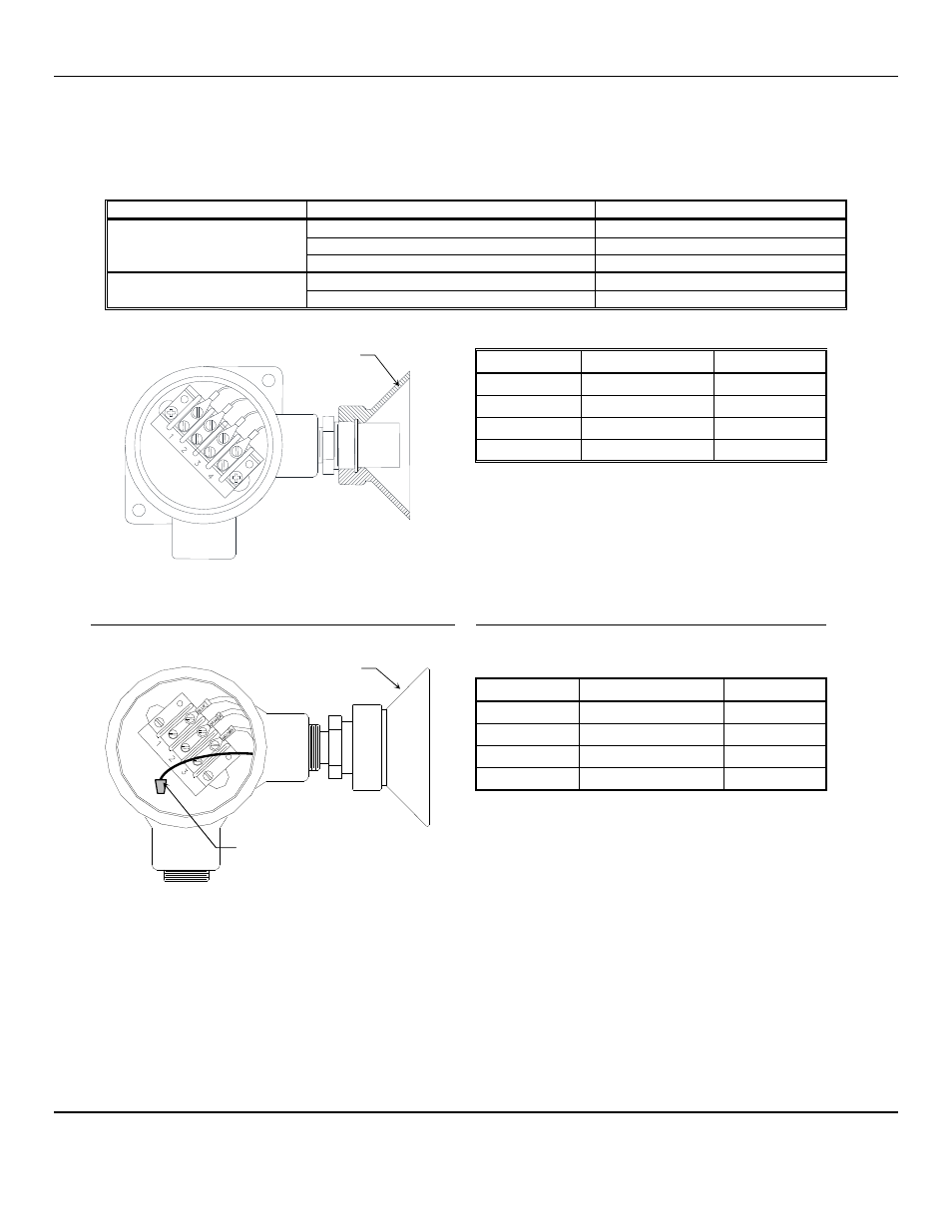
Wiring for 4-wire Terminal Sensors
Position
Function
Wire Color
1
Heater
Orange
2
Signal
Blue
3
Heater Ground
Brown
4
Signal Ground
Yellow
Wiring for 3-wire Terminal Sensors
Position
Function
Wire Color
1
Heater
Orange
2
Signal
Blue
3
Heater Ground
Brown
Wire Nut
Signal Ground
Yellow
N
OTE
:
The yellow signal wire is not connected to the
terminal block, use supplied wire nut.
Figure 5: Internal View of Sensor Wiring
Wire length between the
AM-5150
and the sensor greater then 100ft will require that the sensor heater voltage be reset. After
you mount and install the
AM-5150
and Sensor, you must verify the sensor heater voltage. Use position 2 and 3 to measure
heater voltage.
Locate the sensor heater voltage table label inside the instrument, see Figure 4. Measure the sensor heater voltage at the
sensor, see Figure 5 and adjust the heater adjustment
POT 4
until required voltage is reached, see Figure 4.
Optional
Splash Shield
Sensor Wiring Terminal*
The 4
th
(yellow) wire is not
connected to the terminal
block, use supplied wire nut
Optional
Splash Shield