ENMET AM-5150 User Manual
Page 6
AM-5150
ENMET Corporation
4
3.0 Installation of the AM-5150
The
AM-5150
is supplied with a strain relief for a power line cord. Use this fitting or connect a conduit fitting when supplying
power to the unit.
N
OTE
:
This control panel is N
OT
rated for hazardous locations. The control panel must be located in a NON-Hazardous area.
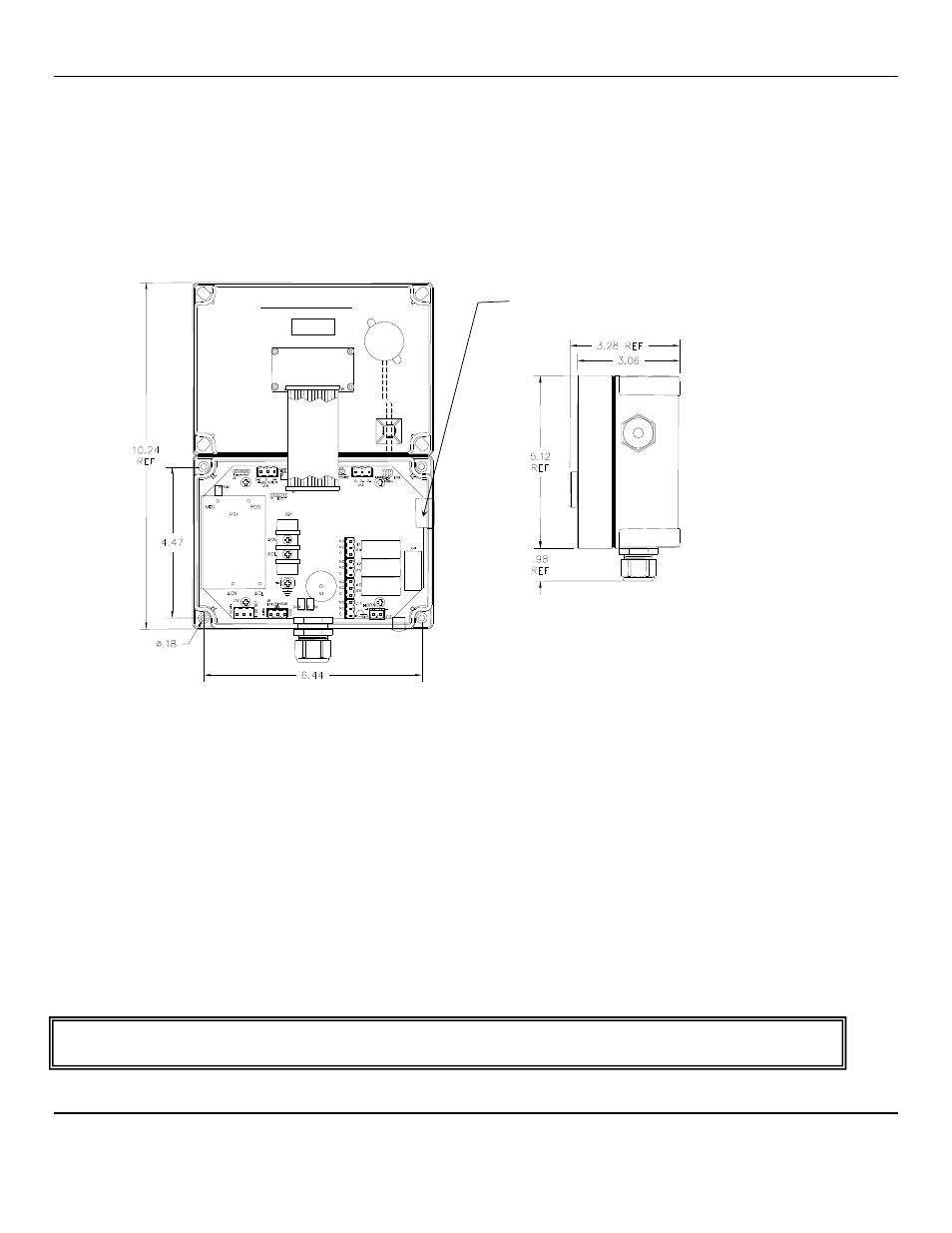
3.1 Mounting AM-5150
Mount the
AM-5150
instrument on an appropriate vertical surface, leaving room for lid to be opened, using the mounting holes
provided. Avoid areas with excessive vibration or temperature extremes. The holes in the bottom of the enclosure are 0.18
inch in diameter and form a 6.44
″ x 4.47″ rectangle. See Figure 3
It is recommended to use #8 drywall anchors and screws for mounting the
AM-5150
to a drywall/sheetrock surface.
Dimensions are in inches.
Figure 3: Mounting AM-5150
3.1.1 Wiring the
AM-5150
The electrical installation should conform to appropriate electrical codes, such as the National Electrical Code in the United
States.
W
ARNING
:
The compliance of the installation to appropriate codes is not
ENMET
’s responsibility.
The
AM-5150
should be powered through circuit breakers provided for this purpose.
3.1.2 Power Supply
The input power can vary from 100 to 240
V
AC
, 50/60 Hz. Power should be connected to the Power Input Terminal
TB1
and
the Ground screw. See Figure 4 for location.
For DC wiring 24
V
DC
may be wired to J12, (J12-1)position 1 + with ground connected to (J12-2)position 2.
Upon supplying power to the
AM-5150
:
The green power on LED is lit.
The display backlight is lit, and instrument will step through a start-up sequence: unit serial number and software revision
may be shown on the display.
The instrument may go into alarm briefly, but the sensors stabilize quickly. If the instrument persists in alarm, acknowledge the
alarm by pressing the
S
ELECT
button. If alarm persists longer than 30 minutes, call
ENMET
customer service personnel.
W
ARNING
:
Continuous gas detection and alarm systems (110
V
AC
/220
V
AC
/ 24
V
DC
/
12
V
DC
powered) become inoperative upon loss of
primary power. Contact factory for specifications and pricing of backup battery systems
.
Right Side View
Cover Inside View
Opened Upward
Attached to Base
Access for Sensor / Remote Sensor Wiring